
Welcome!
This documentation is a resource aimed to get you started with the C.H.I.P. Pro Developer’s Kit. There are lists of contents, descriptions of parts, explanations of how to use the unique features of the board, and some examples to work through so you can get up and running developing your product around C.H.I.P. Pro. Have a C.H.I.P. Pro board but no Dev Kit? Check out the C.H.I.P. Pro documentation site to get started.
Get Started with the C.H.I.P. Pro Dev Kit!
The C.H.I.P. Pro Developer’s Kit provides a complete electronic sandbox to test, iterate, and prototype products with the C.H.I.P. Pro module. While many developer’s kits assume a high-degree of technical experience, we make this kit approachable, compact, and easy to use.
We believe that great products can come from many backgrounds, so we provide several extras in this kit that help you get making and get comfortable. We even include an extra C.H.I.P. Pro to get you started on your own PCB. If you do know it all, you’ll find this documentation will help your product be the best it can be whether you’re making 1 or 1 million.
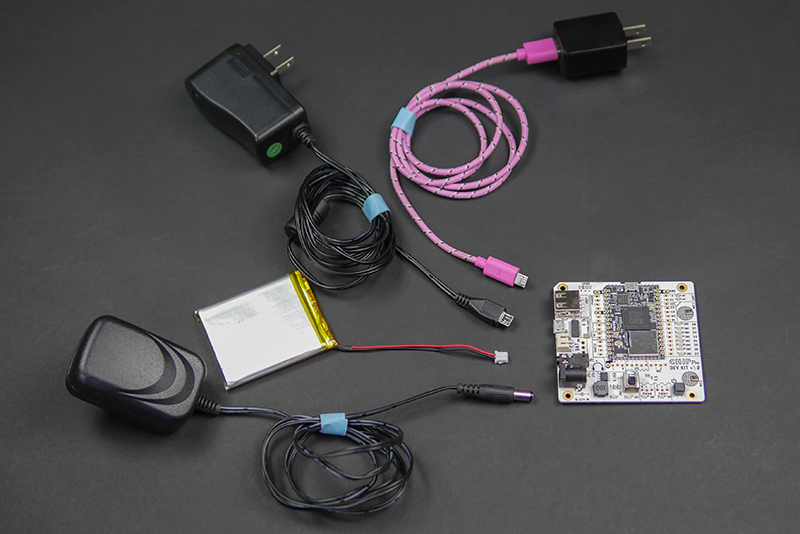
What’s in the Kit
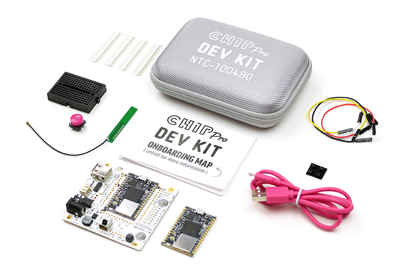
The C.H.I.P. Pro Dev Kit comes with accessories to get you started on your first prototype:
- 1 Dev board with C.H.I.P. Pro soldered on
- 1 C.H.I.P. Pro (loose)
- 4 Male/Female jumper wires
- Male 0.1" pin headers
- 1 Button with cap
- 1 Mini breadboard
- 4 Little Rubber Feet (LRF)
- 1 USB A to Micro-USB B cable
- WiFi Antenna: Wacosun model HCX-P321
- Onboarding Map
Flash With An OS
Before you start building with the C.H.I.P. Pro Dev Kit the C.H.I.P. Pro needs to be flashed with an operating system. We at NTC have built examples that use two operating systems: Buildroot and Debian that are both based on Linux.
Debian is a classic amongst embedded Linux board users for rapid prototyping. It offers a full package manager and loads of precompiled software for many different architectures.
Buildroot is simple and stripped down making it efficient and good for single application use cases.
C.H.I.P. Pro has 512MB of high-reliability SLC NAND storage onboard for holding the core operating system and a limited amount of user and program data. While the storage is faster and more reliable it has less capacity. Because of this, it’s a good idea to know how much storage software will take before flashing and installing. Where needed, additional high-speed storage can be added through C.H.I.P. Pro’s SDIO bus.
Ready to try out some examples? Grab these items, then read on!
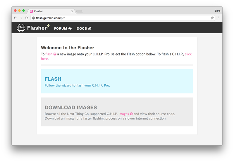
Flashing Process
Head over to the web flasher at flash.getchip.com/pro. If it’s your first time flashing, when you arrive you will be asked to install the NTC Flasher Chrome Extension.
After installing the extension the main page will give you the option to either download an image or follow the wizard to flash C.H.I.P. Pro. For a smooth automated process, click FLASH to flash C.H.I.P. Pro.
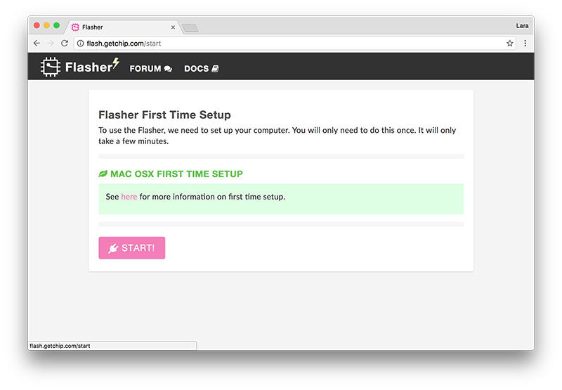
You will be sent to the “Flasher First Time Setup” page which will have instructions dependent on the operating system of your computer. Follow along in the browser or below.
-
Linux-specific
- A Debian-based Linux computer requires creating a set of udev rules to communicate with your C.H.I.P. Pro. Paste the following into a terminal window.
sudo usermod -a -G dialout ${USER}
sudo usermod -a -G plugdev ${USER}

# Create udev rules
echo -e 'SUBSYSTEM=="usb", ATTRS{idVendor}=="1f3a", ATTRS{idProduct}=="efe8", 		GROUP="plugdev", MODE="0660" SYMLINK+="usb-chip"
SUBSYSTEM=="usb", ATTRS{idVendor}=="18d1", ATTRS{idProduct}=="1010", GROUP="plugdev", 	MODE="0660" SYMLINK+="usb-chip-fastboot"
SUBSYSTEM=="usb", ATTRS{idVendor}=="1f3a", ATTRS{idProduct}=="1010", GROUP="plugdev", 	MODE="0660" SYMLINK+="usb-chip-fastboot"
SUBSYSTEM=="usb", ATTRS{idVendor}=="067b", ATTRS{idProduct}=="2303", GROUP="plugdev", 	MODE="0660" SYMLINK+="usb-serial-adapter"
' | sudo tee /etc/udev/rules.d/99-allwinner.rules

sudo udevadm control --reload-rules
Then logout and log back in.
For the curious:
-
${USER}: outputs your username
-
dialout: gives non-root access to serial connections
-
plugdev: allows non-root mounting with pmount
The udev rules then map the usb device to the groups. For more information, check the systems group page on debian.org.
-
Windows-specific
- To communicate to C.H.I.P. Pro from a Windows computer you must install drivers.
- Reboot after installing drivers on previous versions (<10) of Windows.
- During the fastboot process Windows may issue the warning “device not recognized”. Getting this warning during fastboot is normal and flashing should proceed.
-
MacOS specific
- Using USB3 ports can cause the flashing to fail. If you can, try using a USB2 port, not a USB3. If you find yourself with a modern Mac that only has USB3 ports, try using a USB2 hub in your USB3 port and plug C.H.I.P. Pro into that.
- OS X El Capitan has been known to have issue with the flashing process. If a new cable or USB2 hub does not work and you are able to, upgrade to macOS Sierra.
When done with setup, press START!.
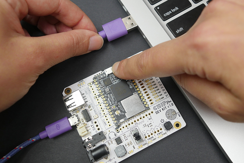
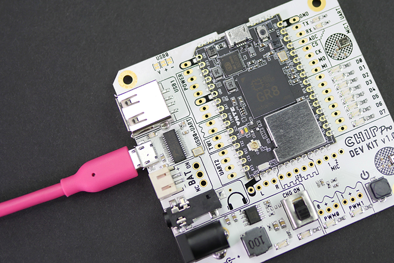
Once the extension is installed, plug the micro USB cable into the USB0 port on the Dev Kit (not on the C.H.I.P. Pro!).
Hold down the FEL button (a pencil eraser works nicely) and with the other hand plug the USB cable into the computer. When the pink power and white status LEDs on C.H.I.P. Pro light up, you can release the FEL button.
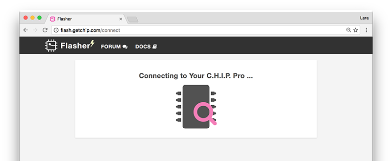
The web flasher will search for and recognize C.H.I.P. Pro.
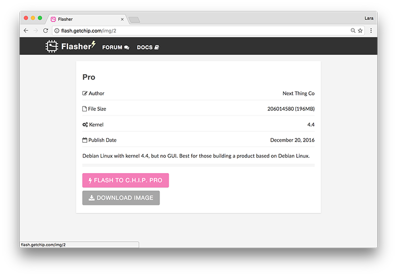
You will then be directed to the page with the example images. Hover over each image to see a description and click to see more details such as file size and kernel version. When you have chosen your adventure, click FLASH TO C.H.I.P. PRO.
[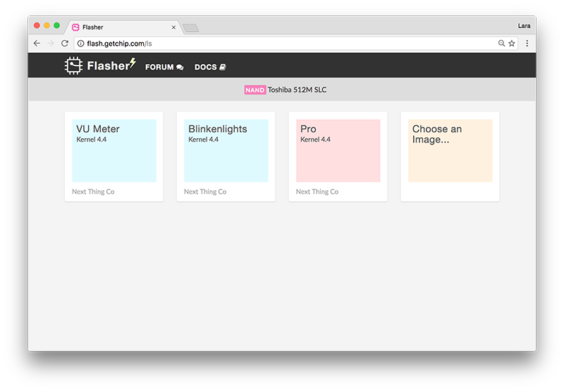 ] (images/imagesPage.jpg) ] (images/imagesPage.jpg) |
[ ] (images/imageDetail.png) ] (images/imageDetail.png) |
|---|---|
| Choose image | Click FLASH TO CHIP PRO |
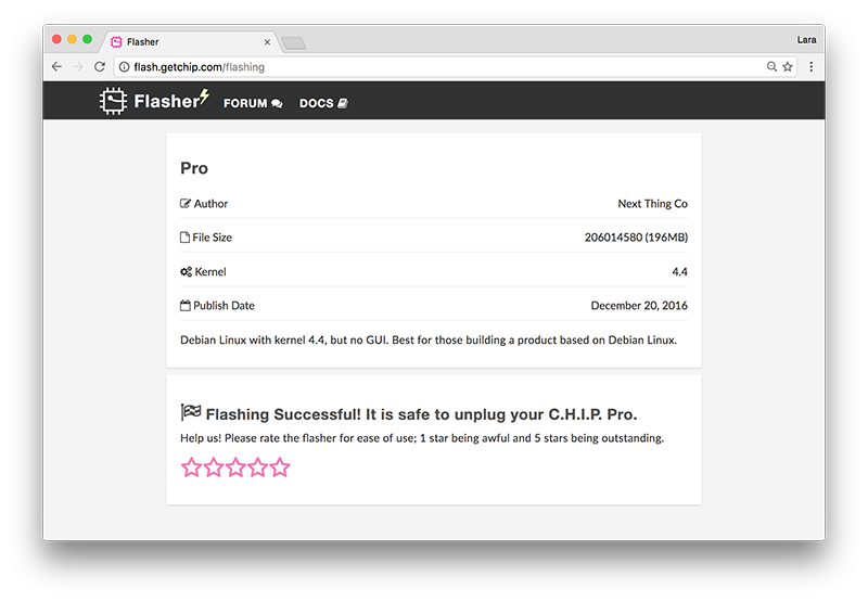
Watch the flashing process progress and leave the browser tab open in order for it to complete. You will be notified when C.H.I.P. Pro has been flashed successfully. You are then free to unplug the C.H.I.P. Pro or connect to it via serial.
If you are having problems with the flashing process follow the troubleshooting instructions given by the web flasher or check out the Web Flasher OS-Specific Issues troubleshooting section.
Examples
You can select an OS by flashing one of our examples using the web flasher flash.getchip.com/pro in Chrome or Chromium browser. Before you go to the web flasher however, there is a method to flashing the C.H.I.P. Pro to know and get in the habit of. This process is explained below and is also illustrated on the flasher page.
Blinkenlights
Controlling LEDs are fundamental to almost any hardware. This simple example provides easy-to-understand code with exciting results! Flash C.H.I.P. Pro with this image and watch the GPIO D0-D7 lights turn on and off in a cascading pattern and the two PWM LEDs pulse from dim to bright. Based on Buildroot.
VU Meter
This example comes with the CHIP_IO library and Python, all in a very small package!
Want to make sure your mics are working? Use this handy VU Meter example. Scream loudly, speak softly, tap the mics, and MAKE SOME NOISE, SPORTSFANS! You’ll see the LEDs light proportional to the volume of the noise captured by the two built-in mics. Based on Buildroot.
Pro
We provide a standard Debian distribution. Once flashed connect to the C.H.I.P. Pro via USB-serial and log in with the default username chip and password chip.
If you want to configure and build the rootfs for the Debian image, take a look at our github repo
After Flashing Image
When you are done or want to flash another example, hold down the power button on the Dev Kit until the Power and Activity LEDs shut off.
Troubleshooting Flashing Fails
If the flashing process fails we have troubleshooting recommendations based on your OS.
Connect and Control
C.H.I.P. Pro is a headless computer, so you will need a separate computer in order to interact with it. This section will go over how to connect to C.H.I.P. Pro Dev Kit through USB-serial, connect to a WiFI network and where to find example scripts on Buildroot.
USB-Serial UART1 Connection
This is the first thing you want to do in order to get your board online and give you access to C.H.I.P. Pro’s software. The Dev Kit has a built-in USB to Serial converter for a direct connection to UART1.
To get started, connect the Dev Kit’s USB0 port (not on the C.H.I.P. Pro!) to your computer with a common USB A to Micro-USB B cable. Next, you will need terminal emulation software on the computer C.H.I.P. Pro Dev Kit is connected to. Find the OS you are using below to see what software is needed and how to connect.
OS X & Linux
Mac systems and most flavors of Linux come with the terminal emulator software Screen. If your Linux distro does not come with Screen and uses Apt install using apt-get:
sudo apt-get install screen
With the Dev Kit connected to your computer, open a terminal window. Find out the tty.usbserial dev path the Dev Kit is attached to:
Mac
ls /dev/tty.*
It will look something like usbserial-DN02ACBB.
Linux
ls /dev/ttyUSB*
The port name is usually ttyUSB0.
Connect
Use Screen to create a serial terminal connection at 115200 bps:
Mac
screen /dev/tty.usbserialxxxxxxxx 115200
Linux
screen /dev/ttyUSB0 115200
Once a terminal window pops up, hit the Enter key twice.
- For a Buildroot example you will automatically be logged in as
root. - For the Debian example, log in with the default username and password
chip.
Exit Screen
When done with Screen, press Ctrl+A then Ctrl+k to kill all windows and terminate Screen.
If you get the error “Cannot open line… Resource busy” when trying to connect via Screen it’s because the last session was not properly exited. Here is how to back and exit properly.
Search for the open file and active process using usbserial:
lsof | grep usbserial
You will get an output that looks something like this:
screen 27127 Sefi 5u CHR 18,0 0t0 605 /dev/tty.usbserial
Note the process ID. In this case, it’s 27127. Then run:
screen -x 27127
This will return you to the previous screen session. Then use Ctrl+A Ctrl+K to close it (will ask you to confirm).
Windows
Download the PuTTY terminal emulator.
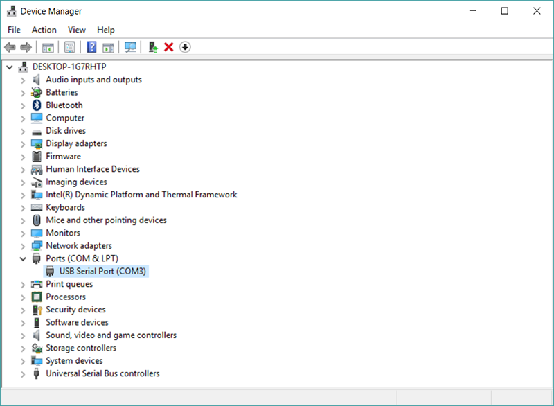
In Windows, open the Device Manager. Find and expand Ports (COM & LPT). Find the port labeled USB Serial Port (COMx) and take note of the COMx port number. This is the port that the C.H.I.P. Pro Dev Kit is connected to.
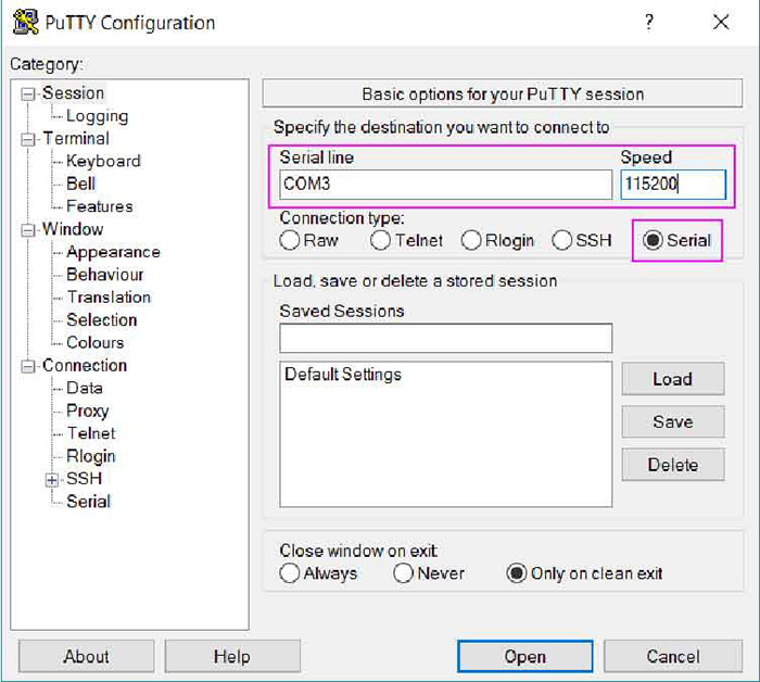
In PuTTY choose Serial as the Connection type. Plug the following items in and click Open.
- COMx number as the Serial Line
- 115200 as the Speed (baud rate)
[ ] (images/ComPort.PNG) ] (images/ComPort.PNG) |
[ ] (images/puTTYsetM.jpg) ] (images/puTTYsetM.jpg) |
|---|---|
| In Device Manager find COM port # | Plug port # and baud rate into puTTY |
Once a terminal window pops up, press Enter.
- For a Buildroot example you will automatically be logged in as
root. - For the Debian example, log in with the default username and password
chip.
Edit Buildroot Examples
After connecting to the Dev Kit via USB-serial you can check out and edit the scripts for each Buildroot example. Use the Vi command-line editor to read and edit example scripts found in /usr/bin.
Blinkenlights
vi /usr/bin/blink-leds
vi /usr/bin/fade-pwms
VU-Meter
vi /usr/bin/vu-meter
Basic Vi Editor Commands
To edit text take Vi from command mode (default) to insert mode. Press the following keys to edit text.
- i - go into insert mode (to edit text)
- Esc - exit insert mode
Vi was built for Qwerty keyboards without arrow keys. They may work but if not, use these keys to move cursor:
- J - move down one line
- K - move up one line
- H - move left one character
- L - move right one character
Other helpful commands:
- u - undo last action
- :x then Enter - save and exit
- :q! then Enter - exit without saving
WiFi Antenna
-
Onboard WiFi and BT ceramic antenna: Unictron product no. H2U34WGTQW0100, model AA055.
-
External antenna included in the C.H.I.P. Pro Dev Kit: Wacosun model HCX-P321.
C.H.I.P. Pro has an onboard ceramic antenna that is intended for debugging purposes only. We recommend the use of an external antenna for all product applications. Use the antenna that comes with the C.H.I.P. Pro Dev Kit or obtain any of these officially supported ones:
| Antenna Model | Manufacturer | Gain | Antenna Type | Connection Type | Freq. Range (GHz) | Cable Length (mm) |
|---|---|---|---|---|---|---|
| AA107 | Unictron | 3.3 dBi | PCB | IPEX | 2.4 - 2.5 | 100 |
| HCX-P321 | Wacosun | 2 dBi | PCB | IPEX | 2.4 - 2.5 | 150 |
| FXP73.07.0100A | Taoglas | 2.5 dBi | PCB | IPEX | 2.4 - 2.483 | 100 |
| AA055 | Unictron | 2.5 dBi | Ceramic | SMT | 2.4 - 2.5 | n/a |
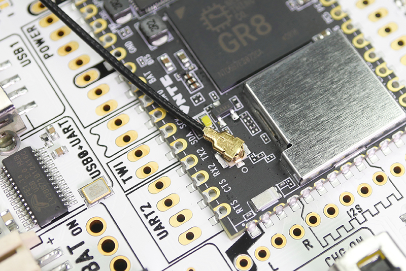
Connect Antenna
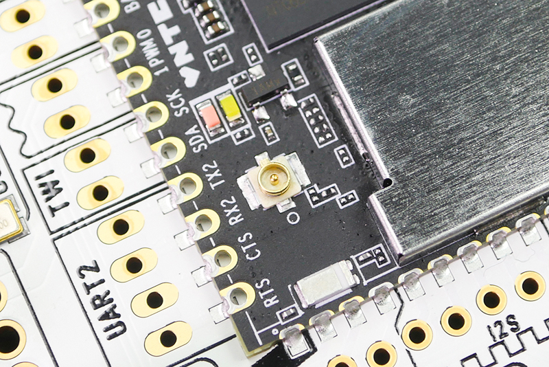
C.H.I.P. Pro uses a standard 50Ω IPEX (Hirose U.FL compatible) connector for the external antenna path.
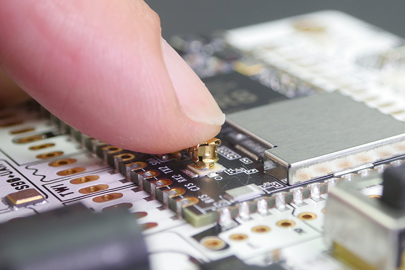
To connect an antenna, come straight from the top and push the antenna onto the connector. Keep in mind the connector will wear out over time. We suggest keeping the disconnect/connect cycle down to 10 or less.
[ ] (images/wifiConnectB.jpg) ] (images/wifiConnectB.jpg) |
[ ] (images/wifiPush.jpg) ] (images/wifiPush.jpg) |
|---|---|
| WiFi antenna connector | Push antenna onto connector |
Enable Wifi Antenna
In order to use it, you need to set the path of the external antenna.
Buildroot
With the Buildroot C.H.I.P. Pro images comes a set_antenna script which accepts two arguments of either pcb or ufl depending on which you want enable.
sh set_antenna pcb|ufl
Debian
In Debian, there are two ways to set the antenna path:
- The RF switch is connected to logic pin PB17. Manually set the logic states to choose either the onboard or external antenna.
0 = onboard-antenna
1 = external-antenna
wgetset_antenna script found here. Run and pass either thepcboruflargument, as stating above.
WiFi Setup: Buildroot
The Buildroot operating system uses the ConnMan command-line network manager to connect and manage your network connections.
Requirements
- C.H.I.P. Pro running buildroot OS
- Serial connection to C.H.I.P. Pro
Step 1: Enable WiFi and Find a Network
These three commands will in turn, enable wifi, scan for access points, and list what networks are available:
connmanctl enable wifi
connmanctl scan wifi
connmanctl services
The services command has output similar to:
WaffleHouse          wifi_xxxxxxxxxxxx_xxxxxx_managed_psk
                	 wifi_xxxxxxxxxxxx_hidden_managed_psk
YOUR_NETWORK         wifi_xxxxxxxxxxxx_xxxxxx_managed_psk
    				 wifi_xxxxxxxxxxxx_xxxxxx_managed_none
Donut_Hut            wifi_xxxxxxxxxxxx_xxxxxxxxx_managed_psk
Step 2: Connect
Copy the string that starts with “wifi_’ to the right of the network name you want to connect to. If it has psk at the end, that means it is password protected (short for Wi-Fi Protected Access 2 - Pre-Shared Key) and you need to scroll further down to the " Password Protected” section.
No Password
For example, to connect to NTC Guest, which has no password, services shows two choices. We want the one without psk in the string. Use the connect command:
connmanctl connect wifi_xxxxxxxxxxxx_xxxxxx_managed_none
If your network is not password protected, you’ll get some output that will indicate a successful connection, such as:
[  961.780000] RTL871X: rtw_set_802_11_connect(wlan0)  fw_state=0x00000008
[  962.070000] RTL871X: start auth
[  962.080000] RTL871X: auth success, start assoc
[  962.090000] RTL871X: rtw_cfg80211_indicate_connect(wlan0) BSS not found !!
[  962.100000] RTL871X: assoc success
[  962.110000] RTL871X: send eapol packet
[  962.290000] RTL871X: send eapol packet
[  962.300000] RTL871X: set pairwise key camid:4, addr:xx:xx:xx:xx:xx:xx, kid:0, type:AES
[  962.320000] RTL871X: set group key camid:5, addr:xx:xx:xx:xx:xx:xx, kid:1, type:AES
If your network is password protected you’ll get an error.
Password-Protected
To deal with passwords you’ll need to put ConnMan into interactive mode:
connmanctl
This command gives a connmanctl prompt:
connmanctl>
In the shell, turn the agent on so it can process password requests:
agent on
Now use the connect command with your pasted wifi network string:
connect wifi_xxxxxxxxxxxx_xxxxxx_managed_psk
Enter your password when prompted:
  Agent RequestInput wifi_xxxxxxxxxxxx_xxxxxx_managed_psk
  Passphrase = [ Type=psk, Requirement=mandatory ]
  Passphrase?
You will be notified that you are connected:
Connected wifi_xxxxxxxxxxxx_xxxxxx_managed_psk
Exit connmanctl interactive mode:
quit
Step 3: Test Connection
Finally, you can test your connection to the internet with ping. Google’s DNS server at the IP address 8.8.8.8 is probably the most reliable computer on the internet, so:
ping -c 4 8.8.8.8
Expect ping to output some timing messages:
PING 8.8.8.8 (8.8.8.8): 56 data bytes
64 bytes from 8.8.8.8: seq=0 ttl=60 time=7.631 ms
64 bytes from 8.8.8.8: seq=1 ttl=60 time=7.474 ms
64 bytes from 8.8.8.8: seq=2 ttl=60 time=7.697 ms
64 bytes from 8.8.8.8: seq=3 ttl=60 time=9.004 ms

--- 8.8.8.8 ping statistics ---
4 packets transmitted, 4 packets received, 0% packet loss
round-trip min/avg/max = 7.474/7.951/9.004 ms
The -c 4 option means it will happen only 4 times.
✨ Congratulations! You are now Connected to a Network ✨
If your connection is not successful, then ping will tell you your network is down:
PING 8.8.8.8 (8.8.8.8): 56 data bytes
ping: sendto: Network is unreachable
Troubleshooting Connection Problems
-
Review any messages that the connect command gave you. Did they look like the examples of a successful connection?
-
Double check that you used the right network with the
connectcommand. -
If everything checked out until you got to
ping, there’s a good chance the problem is with your router or connection to the internet. Some networks have firewalls on them that will allow you to connect but prevent foreign devices from transferring information. -
Connman not Installed Error
If you try to use ConnMan and you get an error that it is not found or is not a command, chances are that you are using the Debian image. The ConnMan commands only apply to C.H.I.P. Pros running the Buildroot OS.
Disconnect from Network with Connman
To disconnect from your network, you might first want a reminder of the unfriendly string used to describe your access point:
connmanctl services
This command will output information about your current connection:
YOUR_NETWORK wifi_xxxxxxxxxxxx_xxxxxx_managed_psk
Copy and paste the string ID along with the disconnect command:
connmanctl disconnect wifi_xxxxxxxxxxxx_xxxxxx_managed_psk
You will be notified when it has disconnected:
Disconnected wifi_xxxxxxxxxxxx_xxxxxx_managed_psk
Forget Network with Connman
Generally, ConnMan will remember and cache setup information. This means that if you reboot in the vicinity of a known network, it will attempt to connect. However, if you need to forget a network setup, navigate to:
cd /var/lib/connman/
You can delete a single connection by seeing which are stored and copying the one you want to delete:
/var/lib/connman # ls
settings
wifi_xxxxxxxxxxxx_xxxxxx_managed_psk
wifi_xxxxxxxxxxxx_xxxxxx_managed_none
Then delete that connection:
rm -r wifi_xxxxxxxxxxxx_xxxxxx_managed_psk
You can delete all the “wifi” connections with:
rm -r wifi*
The -r is needed because these are directories you are deleting and the star at the end of wifi* assumes your connection IDs all start with the string “wifi”.
WiFi Setup: Debian
If you are using the Debian OS you will find that ConnMan is not installed, you will need to use Networking/CLI or the command nmcli instead.
Requirements
- C.H.I.P. Pro loaded with Debian
- Serial connection to C.H.I.P. Pro
Step 1: List available Wi-Fi networks
In terminal type:
nmcli device wifi list
The output will list available access points:
*  SSID      MODE   CHAN  RATE       SIGNAL  BARS  SECURITY
*  YOUR_NETWORK    Infra  11    54 Mbit/s  100     ▂▄▆█  --
   CatCafe         Infra  6     54 Mbit/s  30      ▂___  WPA1 WPA2
   2WIRE533        Infra  10    54 Mbit/s  44      ▂▄__  WPA1 WPA2
Step 2: Connect
You can connect to password protected or open access points.
No Password
To connect to an open network with no password:
sudo nmcli device wifi connect "YOUR_NETWORK_SSID" ifname wlan0
These commands will respond with information about the connection. A successful connection looks like:
Connection with UUID 'xxxxxxxx-yyyy-zzzz-xxxx-yyyyyyyyyyyy' created and activated on device 'wlan0'
Password Protected
To connect to a password protected network, use this command inserting your own network name and password:
sudo nmcli device wifi connect "YOUR_NETWORK_SSID" password "UR_NETWORK_PASSWORD" ifname wlan0
These commands will respond with information about the connection. A successful connection looks like:
Connection with UUID 'xxxxxxxx-yyyy-zzzz-xxxx-yyyyyyyyyyyy' created and activated on device 'wlan0'
Hidden SSID and Password Protected
To connect to a hidden and password-protected network:
sudo nmcli device wifi connect "YOUR_NETWORK_SSID" password "UR_NETWORK_PASSWORD" ifname wlan0 hidden yes
Step 3: Test your Connection
You can verify and test your wireless network connection.
Verify
nmcli device status
This outputs a list of the various network devices and their connections. For example, a successful connection would look like this:
DEVICE   TYPE      STATE         CONNECTION
wlan0    wifi      connected     YOUR_NETWORK
wlan1    wifi      disconnected  --
ip6tnl0  ip6tnl    unmanaged     --
lo       loopback  unmanaged     --
sit0     sit       unmanaged     --
Because it is worth knowing that Linux offers many ways of doing things, another command that shows your current active connection is:
nmcli connection show --active
Which outputs:
NAME  		   UUID                                  TYPE             DEVICE
YOUR_NETWORK   xxxxxxxx-yyyy-zzzz-xxxx-yyyyyyyyyyyy  802-11-wireless  wlan0
After you have connected once, C.H.I.P. Pro will automatically connect to this network next time you reboot (or start NetworkManager services).
Test
Finally, you can test your connection to the internet with ping. Google’s DNS server at the IP address 8.8.8.8 is probably the most reliable computer on the internet, so:
ping -c 4 8.8.8.8
Expect ping to output some timing messages:
PING 8.8.8.8 (8.8.8.8): 56 data bytes
64 bytes from 8.8.8.8: seq=0 ttl=60 time=7.631 ms
64 bytes from 8.8.8.8: seq=1 ttl=60 time=7.474 ms
64 bytes from 8.8.8.8: seq=2 ttl=60 time=7.697 ms
64 bytes from 8.8.8.8: seq=3 ttl=60 time=9.004 ms

--- 8.8.8.8 ping statistics ---
4 packets transmitted, 4 packets received, 0% packet loss
round-trip min/avg/max = 7.474/7.951/9.004 ms
The -c 4 option means it will happen only 4 times.
✨ Congratulations! You are now Connected to a Network ✨
If your connection is not successful, then ping will tell you your network is down:
PING 8.8.8.8 (8.8.8.8): 56 data bytes
ping: sendto: Network is unreachable
Disconnect Network with Nmcli
Disconnect from the wireless device:
sudo nmcli dev disconnect wlan0
Forget Network with Nmcli
You may want to prevent auto-connection to a network. If so, you want the device to forget the a specific network. First, list the connections:
nmcli c
Which outputs something like:
NAME           UUID                                  TYPE             DEVICE
YOUR_NETWORK   xxxxxxxx-yyyy-zzzz-xxxx-yyyyyyyyyyyy  802-11-wireless  wlan0
Then delete the network specified between quotes to forget it:
sudo nmcli connection delete id "YOUR_NETWORK"
Troubleshooting Connection Problems
- No Network Found
No network within range. If there’s no network, you can’t connect. Go find a network!
- Incorrect Password
If you type in the wrong password, you’ll get some errors like this:
[32258.690000] RTL871X: rtw_set_802_11_connect(wlan0) fw_state=0x00000008
[32258.800000] RTL871X: start auth
[32263.720000] RTL871X: rtw_set_802_11_connect(wlan0) fw_state=0x00000008
[32263.820000] RTL871X: start auth
[32264.430000] RTL871X: auth success, start assoc
[32269.850000] RTL871X: rtw_set_802_11_connect(wlan0) fw_state=0x00000008
[32269.970000] RTL871X: start auth
Error: Timeout 90 sec expired.
Try connecting again with the correct password.
- Failed Ping
If you don’t have access to the internet, your ping to an outside IP will fail.
It is possible that you can connect to a wireless network, but have no access to the internet, so you’d see a connection when you request device status, but have a failed ping. This indicates a problem or restriction with the router or the access point.
A failed ping looks something like:
From 192.133.2.10 icmp_seq=14 Destination Host Unreachable
From 192.133.2.10 icmp_seq=15 Destination Host Unreachable
From 192.133.2.10 icmp_seq=16 Destination Host Unreachable
18 packets transmitted, 0 received, +9 errors, 100% packet loss, time 17013ms
pipe 4
Change the router or access point permissions to allow a foreign board to connect to it. Alternatively, a personal mobile hotspot can obtained and used if you are in a work environment that can not change its network security settings.
- Loss of Wireless Network
A sudden, unplanned disconnection will post an error in the terminal window:
[30863.880000] RTL871X: linked_status_chk(wlan0) disconnect or roaming
The Network Manager will periodically try to reconnect. If the access point is restored, you’ll get something like this in your terminal window:
[31798.970000] RTL871X: rtw_set_802_11_connect(wlan0)
[31799.030000] RTL871X: start auth
[31799.040000] RTL871X: auth success, start assoc
[31799.050000] RTL871X: rtw_cfg80211_indicate_connect(wlan0) BSS not found !!
[31799.060000] RTL871X: assoc success
- Nmcli not Installed Error
If you try to use nmcli and you get an error that it is not found or is not a command, chances are that you are using a C.H.I.P. Pro Buildroot image. The nmcli commands only apply to C.H.I.P. Pro using Debian linux.
SSH
Once you connect to an network you can ssh into the C.H.I.P. Pro in order to program and control it. Our Debian example comes with ssh servers, our Buildroot examples do not. If you want to ssh while using Buildroot you will need to do a manual build.
Find IP
ip addr
The IP is on wlan0 or sometimes on wlan1.
Connect
ssh root@<CHIPproIP>
Audio
The C.H.I.P. Pro Development Kit has several ways to access audio in and out. Stereo audio in and out is handled by a 24-bit DAC built-in to the GR8 processor. There are also digital options that you can use, but require configuration of the Linux kernel and additional hardware to access.
- Audio output via 3.5mm TRRS jack
- Mono input via 3.5mm TRRS jack
- Stereo microphones
- MIC1 and MIC2 header pins
- I2S digital audio
- SPIDIF digital audio
Input
There are two (2) analog MEMS (micro electro mechanical) microphones on the Dev Kit. These are enabled by default.
If you want to use the MIC1 and MIC2 pins for audio input, you’ll need to cut a trace.
The “Sleeve” (bottom-most ring) on the TRRS jack can be used as a mono audio input, suitable for microphones commonly built-in to headphones. If you want to used this connector, you’ll need to cut a trace.
Output
The 3.5mm TRRS jack provides stereo output suitable for headphones or amplification to stereo speakers.
USB Accessories
The USB1 port can be used to connect and use popular accessories like storage, MIDI controllers, keyboards, pointing devices, audio hardware, and more. C.H.I.P. Pro does not provide power to the USB1 port on its own, so the Development Kit is a good example of how this works.
USB1 Power
USB1 is provided with 5V from pass-through of the 5V supplied to the USB0+UART micro USB port on the devkit pcb
For high-load devices attached to USB1, make sure an adequate power supply is provided. For example, when you plug in a keyboard and an optical mouse, they will draw too much current from the C.H.I.P. Pro Dev Kit, not leaving enough for the processor. As a result, C.H.I.P. Pro will immediately shut down. There are a few ways to avoid this.
- Use a powered USB hub
- Use a bluetooth keyboard and mouse. Yes, this is a very specific solution, but a good one when you are only using the USB port for keyboard and mouse. Keeps your desk cleaner too!
- Execute the command
sudo axp209 --no-limitin the terminal before you attach your USB peripherals. - Provide power from a supply connecting ground and 4.8V to 6V to the CHG-IN , pin 4.
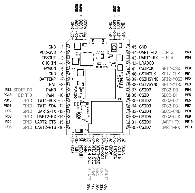
GPIO
C.H.I.P. Pro has a total of 27 GPIO pins ready for use:
- 2 PWM
- pins 9 & 10
- 3 input
- pins 39 - 41
- 22 input/output
- pins 11-16, 21-25, 30-38, 43 & 44
To see all the functions C.H.I.P. Pro pins offer check out the Multiplexing table.
Interacting with Sysfs
The Linux kernel provides a simple sysfs interface to access GPIO from. Depending on the image flashed to C.H.I.P. Pro, the commands used to interact with the sysfs interface will differ. If using the Pro image, you need to act as root and use sudo sh -c with quotes around the command string. For example:
Pro (Debian)
sudo sh -c 'echo 132 > /sys/class/gpio/export'
Buildroot:
echo 132 > /sys/class/gpio/export
Follow along with the examples to learn more about sysfs including how to directly read and write to sysfs. All examples in the GPIO documentation are done using one of NTC’s Buildroot based images.
GPIO Sysfs Numbers
To address a GPIO port via sysfs, you do not use the C.H.I.P. Pro or GR8 pin name. Sysfs sees the pins as another set of numbers. To find out what number to use for each GPIO pin reference the tables below.
Sysfs Pin Numbers
D0 - D7:
| C.H.I.P. Pro Pin # | 37 | 36 | 35 | 34 | 33 | 32 | 31 | 30 |
|---|---|---|---|---|---|---|---|---|
| sysfs # | 132 | 133 | 134 | 135 | 136 | 137 | 138 | 139 |
TWI1, UART2:
| C.H.I.P. Pro Pin # | 11 | 12 | 13 | 14 | 15 | 16 |
|---|---|---|---|---|---|---|
| sysfs # | 47 | 48 | 98 | 99 | 100 | 101 |
I2S:
| C.H.I.P. Pro Pin # | 21 | 22 | 23 | 24 | 25 |
|---|---|---|---|---|---|
| sysfs # | 37 | 38 | 39 | 40 | 41 |
SPI2:
| C.H.I.P. Pro Pin # | 41 | 40 | 39 | 38 |
|---|---|---|---|---|
| sysfs # | 128 | 129 | 130 | 131 |
PWM:
| C.H.I.P. Pro Pin # | 9 | 10 |
|---|---|---|
| sysfs # | 0 | 1 |
UART1:
** These pins are connected to the FE1.1S USB hub controller IC which is connected to the micro USB providing USB serial functionality. To use them as GPIO disable the USB hub controller by cutting the “UART Disconnect” traces.
| C.H.I.P. Pro Pin # | 44 | 43 |
|---|---|---|
| sysfs # | 195 | 196 |
Calculate sysfs Number
If a pin is not listed above you can calculate the sysfs number starting with the GR8 port number. All port numbers are printed on C.H.I.P. Pro for your convenience. They can also be found in the Allwinner R8 Datasheet starting on page 15.
As an example, take a look at D0 which is port PE4. Look at the letter that follows the “P”, in this case it’s “E”. Starting with A = 0, count up in the alphabet until you arrive at “E” and that is the letter index. For example, E=4.
Multiply the letter index by 32, then add the number that follows “PE”:
(4*32)+4 = 132
Export Digital GPIOs
The GPIO control interface can be found at /sys/class/gpio. To explore the sysfs file structure, connect to C.H.I.P. Pro via USB-serial and in a terminal window type:
ls /sys/class/gpio
In the gpio directory you will find:
- export - Allows a GPIO signal to be read and written to.
- unexport - Reverses the effect of exporting.
To read and write to a pin it must first be exported. As an example, use the sysfs number 132 to export pin PE4:
echo 132 > /sys/class/gpio/export
Once exported, a GPIO signal will have a path like /sys/class/gpio/gpioN where N is the sysfs number. In the gpioN directory, you can see what attributes are available to read and write to:
ls /sys/class/gpio/export/gpio132
- direction - Set direction of pin using “in” or out". All GPIOs are I/Os except for PE0, PE1 and PE2 which are input only.
- value - Value of pin written or read as either 0 (low) or 1 (high).
- edge - Written or read as either “non”, “rising”, “falling”, or “both”. This attribute only shows up when the pin can be configurred as an interrupt.
- active_low - Reads as either 0 (false) or 1 (true). Write any nonzero value to invert the value attribute both for reading and writing.
Learn more about the sysfs interface here.
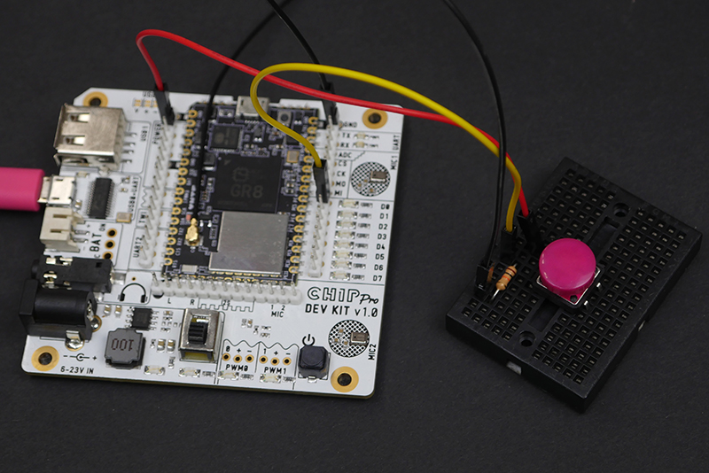
Digital Input Example
The following example goes through a general command sequence to read the changing state of a pin. This example reads a switch connected to PE4. When wiring up a switch, add an external pull-up or pull-down resistor to prevent a floating pin logic state. The photo below shows a pull-down resistor.
In terminal, tell the system you want to listen to a pin by exporting it:
echo 132 > /sys/class/gpio/export
Next, the pin direction needs to be set. Use cat to read what direction the pin is currently set to:
cat /sys/class/gpio/gpio132/direction
Switch the pin’s direction to “in”:
echo in > /sys/class/gpio/gpio132/direction
Connect a switch between pin PE4 and GND and read the value:
cat /sys/class/gpio/gpio132/value
Continuously check the value of the switch pin for its state change:
while ( true ); do cat /sys/class/gpio/gpio132/value; sleep 1; done;
Unexport:
echo 132 > /sys/class/gpio/unexport
Digital Output Example
Onboard LEDs
The Dev Kit provides ten onboard LEDs to make testing the GPIOs easy without having to wire anything up. Eight of these LEDs are connected to digital I/O pins that can be turned on and off with standard Linux sysfs commands.
- Pins 30 - 37 which are seen as 132 - 139 in sysfs.
Blinkenlights Image
To start with an example that demos the eight I/Os and two PWM onboard LEDs, flash C.H.I.P. Pro Dev Kit with the Blinkenlights image and view the example scripts using the command-line editor Vi.
Turn LED On and Off
Follow along to turn on and off the LED attached to pin 37.
Export the pin and change the mode from "in” to “out”:
echo 132 > /sys/class/gpio/export
echo out > /sys/class/gpio/gpio132/direction
Now that it’s in output mode, you can write a value to the pin and turn the LED on and off:
echo 1 > /sys/class/gpio/gpio132/value
echo 0 > /sys/class/gpio/gpio132/value
Unexport:
echo 132 > /sys/class/gpio/unexport
Blink
After exporting a pin run this to blink an LED on pin 37.
while ( true ); do echo 1 > /sys/class/gpio/gpio132/value; cat /sys/class/gpio/gpio132/value; sleep 1; echo 0 > /sys/class/gpio/gpio132/value; cat /sys/class/gpio/gpio132/value; sleep 1; done;
Unexport GPIO
If pins have not been unexported an error will occur stating the pins are “busy” the next time you go to export them. When you are done using a GPIO pin always tell the system to stop listening by unexporting it:
echo 132 > /sys/class/gpio/unexport
PWM
C.H.I.P. Pro can output a PWM signal up to 24 MHz on two pins: PWM0 and PWM1. The Dev Kit also features two places to connect servos that provide the power needed to drive them.
PWM via sysfs
Depending on the image that is flashed to C.H.I.P. Pro, the commands used to interact with the sysfs interface will differ. If using a Pro image, you need to act as root and use sudo sh -c with quotes around the command string. For example:
Pro (Debian)
sudo sh -c 'echo 0 > export' #PWM0
Buildroot:
echo 0 > export #PWM0
All PWM examples are done using one of NTC’s Buildroot based images.
Export PWM Channel
The Linux kernel provides a simple sysfs interface to access PWM from. The PWM controller can be found exported as pwmchip0 at /sys/class/pwm/pwmchip0. To test the PWM channels and explore the sysfs file structure, connect to C.H.I.P. Pro via USB-serial and in a terminal window type:
ls /sys/class/pwm/pwmchip0
In the pwmchip0 directory you will find:
- export - Allows a PWM channel to be read and written to.
- unexport - Reverses the effect of exporting (always do this after you are done using a channel).
- npwm - Says how many PWM channels are available.
You can see there are two PWM channels available from C.H.I.P. Pro’s PWM controller/chip by using cat:
cd /sys/class/pwm/pwmchip0
cat npwm
Before you can use a channel you need to export it. Use these numbers to reference which pin you would like to export:
| C.H.I.P. Pro Pin # | 9 | 10 |
|---|---|---|
| sysfs # | 0 | 1 |
echo 0 > export #PWM0
ls
After exporting, you will find that a new directory pwmX, where X is the channel number, has been created. Go into the pwmX directory to check out the attributes available for use:
cd pwm0
ls
In the pwmX directory you will find:
-
duty_cycle - The active time of the PWM signal in nanoseconds. Must be less than the period.
-
enable - Enable/disable the PWM signal using either 0 or 1.
0 - disabled
1 - enabled
-
period - Total period of inactive and active time of the PWM signal in nanoseconds.
-
polarity - Changes the polarity of the PWM signal. Value is “normal” or “inversed”.
To test the PWM channels follow the examples below.
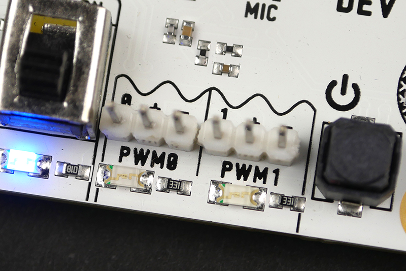
PWM LED Example
There are two onboard LEDs connected to the PWM pins for testing and learning about pulse width modulation. You can disconnect these PWM LEDs at any time by cutting traces.
Export a channel, set the polarity and enable PWM0:
echo 0 > /sys/class/pwm/pwmchip0/export
echo "normal" > /sys/class/pwm/pwmchip0/pwm0/polarity
echo 1 > /sys/class/pwm/pwmchip0/pwm0/enable
Set the period to 10000000 nanoseconds (1 second) and the duty cycle to 0:
echo 10000000 > /sys/class/pwm/pwmchip0/pwm0/period
echo 0 > /sys/class/pwm/pwmchip0/pwm0/duty_cycle
From here, set the duty_cycle in nanoseconds. Start dim at 1% and step up to the 100%:
echo 100000 > /sys/class/pwm/pwmchip0/pwm0/duty_cycle
echo 500000 > /sys/class/pwm/pwmchip0/pwm0/duty_cycle
echo 1000000 > /sys/class/pwm/pwmchip0/pwm0/duty_cycle
echo 5000000 > /sys/class/pwm/pwmchip0/pwm0/duty_cycle
echo 10000000 > /sys/class/pwm/pwmchip0/pwm0/duty_cycle
Disable and unexport:
echo 0 > /sys/class/pwm/pwmchip0/enable
echo 0 > /sys/class/pwm/pwmchip0/unexport
PWM Servo Examples
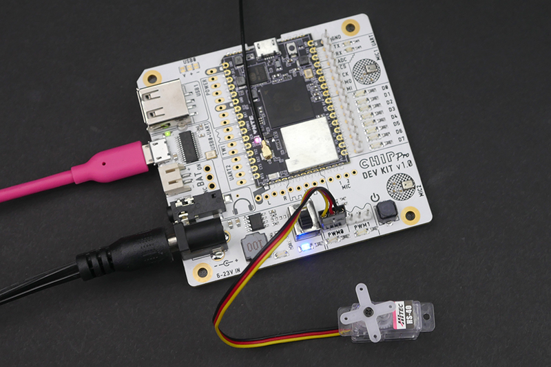
The C.H.I.P. Pro Dev Kit provides breakout pins to conveniently power and control servos.
Most servos have three pins: power, ground, and a control signal. The control signal is a pulse-width-modulated input signal whose high pulse width (within a determined period) determines the servo’s angular position. The control signal pin draws a small enough amount of current that it can be directly controlled by the PWM pins on C.H.I.P. Pro.
While the control signal pin draws a low amount of power, the servo motor draws more power than the C.H.I.P. Pro can provide on its own. The Dev Kit helps with this by providing a 5 volt power pin next to the signal and ground pin. This pin is connected to the DC-In barrel jack.
The PWM0 and PWM1 through-holes are staggered just enough to friction hold male header pins. No soldering needed! (•◡•)/
Setup PWM Channel
Export the PWM pin you want to use:
echo 0 > /sys/class/pwm/pwmchip0/pwm0/export
Enable the channel and set the polarity, period of the waveform and duty cycle. Units are in nanoseconds. The polarity can only be set before the pin is enabled. If you set it after enabling a pin the script should still work but you will see a “I/O error”. Most servos operate at 50Hz which translates into a 20000000 ns period. Start the duty cycle at 0:
echo normal > /sys/class/pwm/pwmchip0/pwm0/polarity
echo 1 > /sys/class/pwm/pwmchip0/pwm0/enable
echo 20000000 > /sys/class/pwm/pwmchip0/pwm0/period
echo 0 > /sys/class/pwm/pwmchip0/pwm0/duty_cycle
Once you do this initial setup, to rotate the servo change the duty_cycle. Whatever value is written to the duty_cycle changes the active time of the PWM signal. To get you started, there are two examples below, one rotates a 180º servo, the other rotates and stops a 360º continuous servo.
180º Servo
Servo Used in Example
- 180º degree 4.8V - 6V Hitec HS-40
Before you start to work with your servo, check the servo’s datasheet. There you can sometimes find the pulse width range needed to control it.
To rotate 180º most servos require a duty cycle where 1000000 ns/1 ms corresponds to the minimum angle and 2000000 ns/2 ms corresponds to the maximum angle. However, not all servos are the same and will require calibration. For example, the HS-40 used in this example has a minimum of 600000 ns/0.6 ms and maximum of 2400000 ns/2.4 ms. A good place to start is somewhere in the middle like 1500000 ns/1.5 ms. You can then go up and down from there to find the max. and min.
Change the duty cycle to 1500000 ns and step up every 100000 ns to move the servo:
echo 1500000 > /sys/class/pwm/pwmchip0/pwm0/duty_cycle
echo 1600000 > /sys/class/pwm/pwmchip0/pwm0/duty_cycle
echo 1700000 > /sys/class/pwm/pwmchip0/pwm0/duty_cycle
When done, disable and unexport pin:
echo 0 > /sys/class/pwm/pwmchip0/pwm0/enable
echo 0 > /sys/class/pwm/pwmchip0/unexport
Sweep Script
This script rotates a servo on PWM0 from 0º to 180º while printing the duty cycle. Press Ctrl+C to unexport PWM0 and exit the script. You may need to calibrate the minimum and maximum to fit your servo.
360º Continuos Servo
Servo Used in Example
- 360º Continuous 4.8V - 6V FEETEC FS90R Micro Servo
For a continuous servo the PWM input signal controls the speed, direction of rotation and stopping period. Before you start to work with your servo, check the servo’s datasheet. There you can sometimes find the pulse width range needed to control it.
A typical stop width is 1500000 ns/1.5 ms. The further the time travels above and below the stop width, the slower the rotation speed gets.
Below are the times for the FS90R servo. Yours may be slightly different. A good place to start is 1500000 ns and going 100000 ns up and down from there to find the stop, right and left pulse times.
- 1500000 ns: stop
- 1000000 ns - 1400000 ns: slow - fast right
- 1600000 ns - 2000000 ns: slow - fast left
Sweep Script
This script steps a servo connected to PWM0 through different speeds while rotating in each direction. Press Ctrl+C to unexport PWM0 and exit script. Each speed lasts for two seconds. It stops for one second at 1500000 ns before rotating in the opposite direction.
Unexport PWM
If pins have not been unexported an error will occur stating the pins are “busy” the next time you go to export them. When you are done using a PWM pin always tell the system to stop listening by unexporting it:
echo 0 > /sys/class/gpio/unexport #PWM0
Power
Powering Off
After C.H.I.P. Pro has been flashed with a new image you can power off the board by holding the power button on the dev board down (for about 5 seconds). Wait for the power and status LEDs to turn off.
If running processes while connected to C.H.I.P. Pro we recommend powering off C.H.I.P. Pro via command line:
Buildroot
poweroff
Debian
sudo poweroff
In this instance the software puts all processes away properly making it is safe to remove the power supply from the Dev Kit without the risk of losing data.
Power C.H.I.P. Pro Dev Kit
There are three ports on the Dev Kit that support three different power supplies:
- Micro USB port - Use either an AC/DC adapter or powered USB hub with a micro USB plug.
- JST-PH 2.0mm - Connect a rechargeable 3.7V lithium polymer battery to the JST port. Press the On/Off button to power C.H.I.P. Pro. Charge a LiPo battery connected to this port by connecting an AC adapter to the barrel jack.
- DC-IN barrel jack - Plug in a 6 - 23V AC/DC adapter (we recommend getting one that supplies 12V and 1 amps).
Power can also be provided to three pins to power C.H.I.P. Pro:
- CHG-IN - connect 4.8 to 6 V of power to pin 4 (and GND) to provide power to C.H.I.P. Pro. If you have a 3.7V Lithium Polymer (LiPo) battery connected to BAT, then power provided to CHGIN will also charge the battery.
- BAT - connect a 3.7V Lithium Polymer (LiPo) battery to pin 8 (and GND) to provide power to C.H.I.P. Pro. You can charge the battery by providing voltage to the CHG-IN pin. When a battery is connected, short the PWRON (PWR) pin to ground for 2 seconds to start current flow.
- VBUS - connect 5V to pin 50 (and GND to pin 53) to provide power to C.H.I.P. Pro.
Power Out
The C.H.I.P. Pro Dev kit can provide power to sensors and peripherals.
- VCC-3V3 - pin 2 provides 3.3V for sensors and anything else. This pin can provide a maximum of 800mA. The 800mA supply takes into account system load and can vary depending on what the Wifi module and GR8 SOC are requiring from the AXP209 power management IC.
- For your servo needs PWM0 and PWM1 breakout through-holes provide 5V volts and 2.5A.
- IPSOUT - pin 3, this is AXP209’s Intelligent Power Select pin. It automatically supplies current from available sources based on logic set in the registers.
- USB1 Host - provide power to USB peripherals.
- PWRON - connect to ground to turn C.H.I.P. Pro on and boot the operating system.
Battery Charging and BTS Pin
The Dev Kit uses the AXP209 IC to manage charging. Pin 7 marked BATTEMP or BTS is directly connected to the TS pin on the AXP209. This pin supports a thermistor to monitor the battery temperature when the battery is charging or discharging. If you do not incorporate a thermistor into your setup the pin may float from ground interferring with how much charge current is throttled to the BAT pin and the JST connector. To ensure maximum charge current without a thermistor disable the battery temperature monitoring system.
There are two ways to do this:
- Connect BTS pin to ground
- Disable the temperature functionality in software:
sudo i2cset -y -f 0 0x34 0x82 0x82
The AXP209 IC is seen as a I2C device on C.H.I.P. Pro. By default the AXP209 is tuned for a 10KΩ 1% thermistor at 25°C with a programmable register for thermistor current to adapt to different devices. You can find more information on this setup in the AXP209 Datasheet. Search “ts pin” to quickly find information.
AXP209 Power Management
There are several ways to power the C.H.I.P. Pro Dev Kit and your creative endeavors. The Dev Kit boasts a AXP209 Power System Management IC designed to switch to any available power source. The following table details what happens with some different power scenarios.
| Power Source | Result |
|---|---|
| Battery | C.H.I.P. Pro is powered by battery, USB1 does not receive 5V |
| Battery + DC In | C.H.I.P. Pro is powered by DC In, battery can be charged up to 1.8A |
| Battery + USB In | C.H.I.P. Pro is powered by USB in, battery can be charged up to 900mA by default, more if the no-limit setting is used |
| Battery + DC In + USB In | C.H.I.P. Pro is powered by DC In, battery is charged |
| Battery + low amperage DC or USB In | Battery powers C.H.I.P. Pro as needed to prevent shut down |
Overvoltage can cause permanent damage. Find more details for each port’s specifications in the C.H.I.P. Pro datasheet and AXP209 Datasheet.
Technical Documents
Dev Kit Component Datasheets
Find all the datasheets to the components found on C.H.I.P. Pro Dev Kit here.
Dev Kit Schematics and Design Files
The schematics for C.H.I.P. Pro Dev Kit are available in easy to read PDFs or Eagle design files.
C.H.I.P. Pro Datasheet
The complete datasheet for C.H.I.P. Pro is available in our C.H.I.P. Pro Hardware GitHub repo.
Open Source License
C.H.I.P. Pro Dev Kit is open source hardware and software. Find all you need to build a C.H.I.P. Pro Dev Kit in our Github repo. The Dev Kit is powered by C.H.I.P. Pro. Find all technical documents for C.H.I.P. Pro in its own dedicated repository. Search our repositories for core and developing software. For up-to-date announcements on software releases visit our website and sign up to our newsletter. Or, join the community on our forum where we actively post announcements.

This work is licensed under a Creative Commons Attribution 4.0 International License.
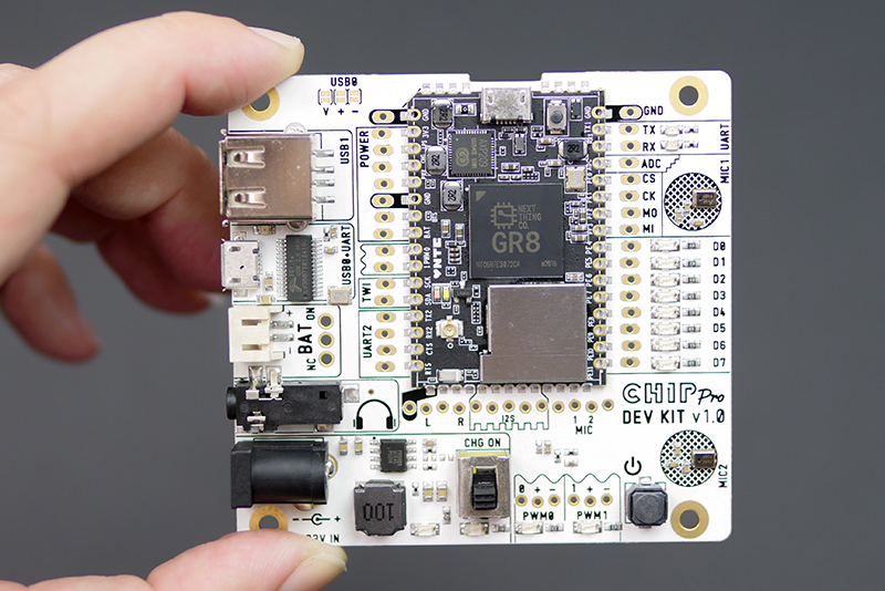
What’s on the Board
C.H.I.P. Pro Dev Kit Features
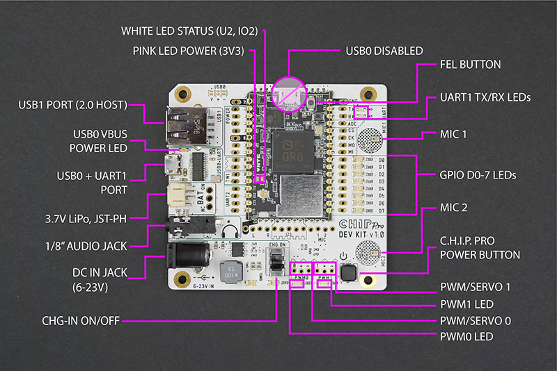
- USB1 Port (2.0 Host) - USB A jack lets C.H.I.P. Pro act as a USB EHCI/OHCI host for external devices. By default, this is powered by the USB micro jack. Cut the appropriate trace to power this from the barrel jack instead.
- USB0 VBUS Power LED - When there is power available to the USB1 port, this LED will illumniate.
- USB0 + UART1 - The micro USB jack provides serial and USB gadget connectivity, power from a USB power source, and UART connectivity for complete terminal messages from boot time.
- 3.7 LiPo battery jack - a JST connector for connecting and powering the dev kit from a 3.7 volt Lithium Polymer battery.
- 1/8" Audio Jack - This TRRS jack provides stereo audio out and optional mono input.
- DC In Jack - Connect a power supply ranging from 6V to 23V to power the C.H.I.P. Pro.
- CHG-IN On/Off Switch - Switch can enable or disable the power feed from the DC in jack, allowing you to isolate the power source.
- PWM0/1 LEDs - Two LEDs are connected directly to the PWM pins on C.H.I.P. Pro to make it easy to test PWM in software by dimming these LEDs.
- C.H.I.P. Pro Power Button - If there is power from DC, USB, or battery, you can hold this down for 1 second to turn C.H.I.P. Pro on, or hold for 5 seconds to turn it off.
- MIC1/2 - Two on-board microphones are spaced 40mm apart, ideal for testing voice control applications and beam-forming algorithms. (With sound travelling at ~340 m/s, the delay between the two microphones is 5.64 samples @ 48K sampling rate, or 117 microseconds)
- GPIO D0-7 LED - These are connected directly to GPIO D0 to D7 on C.H.I.P. Pro for easy software examples using GPIO control.
- UART1 TX/RX LEDs - These LEDs indicate when data is passing on the UART1 TX and RX pins.
- FEL Button - This button needs to be held down before C.H.I.P. Pro is powered up to put it in FEL mode for flashing new firmware.
Pin Headers
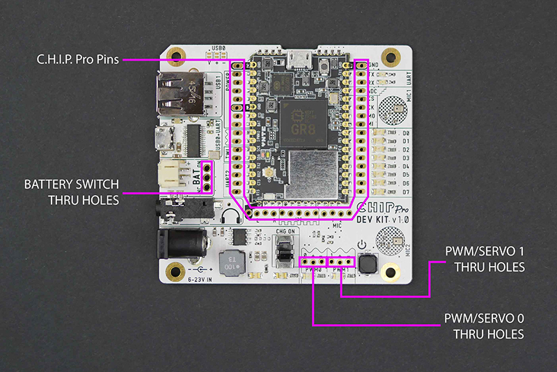
There are several areas where pin headers can be soldered into through-holes for easy access and control of the pins on C.H.I.P. Pro.
- PWM0/1 Through-Hole Breakout - Add pin headers to connect servos and LEDs with pulse width modulation.
- Battery Switch - Add a switch so you can easily disable or enable power from a battery. You will need to cut a trace to make this switch work.
- C.H.I.P. Pro - The through-holes surrounding the C.H.I.P. Pro can be filled with pin headers to give access to the pin you need.
Cuttable Traces
The C.H.I.P. Pro Dev Kit is designed to be flexible for your design and provide valuable built-in hardware. There are several cuttable circuit paths that will disconnect onboard components and reroute power and data to where you need. You can find all of the cuttable paths jumpers outlined in the images below.
Default circuit paths are indicated with a silkscreened bar under the connected pads.
Most of these traces are on the back of the board with one very important exception. The USB0 jumpers on the front are connected to the micro USB0 port on the Dev Kit. This renders the micro USB port on the C.H.I.P. Pro itself unusable. If you would like to use the micro USB port on C.H.I.P. Pro these must be cut.
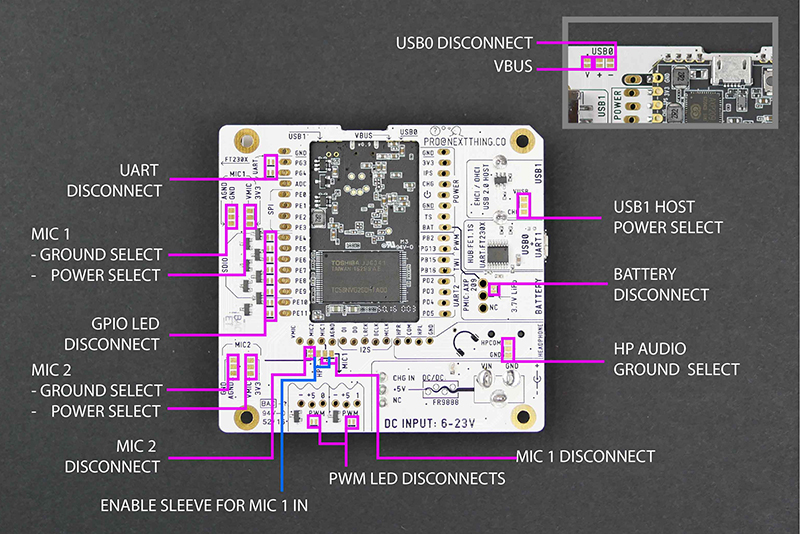
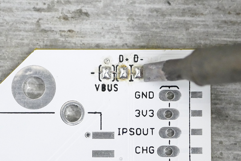
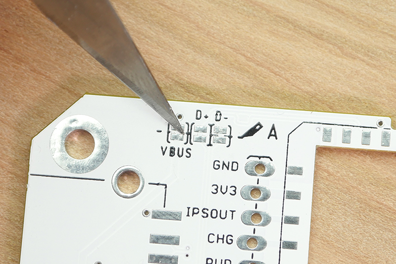
Front Traces
- USB0 Disconnect - There are two traces that are important for USB communication and one (1) trace that will disconnect USB power from the main micro USB connnector to C.H.I.P. Pro. To disconnect the dev kit’s main micro USB connector, cut between the pads for the traces marked “+” and “-”. These are for the “D+” and “D-” USB data lines. This will allow you to use the micro USB connector on the C.H.I.P. Pro.
Back Traces
- UART Disconnect - Cut these traces to disable the UART functionality from the dev kit’s USB micro connector. This disables the FE1.1S USB hub controller IC.
- MIC1/MIC2 Power Select - Cut-and-solder these pads to change the power source for the onboard mics. Cut between the pads marked with the line, then solder bridge the other two pads to select 3.3 volt power instead of the default VMIC power for MIC1 or MIC2. By default the dev kit is wired to VMIC which provides power only while recording.
- MIC1/MIC2 Ground Select - Cut-and-solder these pads to change the ground for the onboard mics. Cut between the pads with the line, then solder between the other two pads to select GND instead of the default AGND power for MIC1 or MIC2.
- GPIO LED Disconnect - If you don’t want the on-board GPIO LEDs to illuminate, cut this trace.
- MIC2 Disconnect - Cut this trace to disconnect the onboard microphone and enable the MIC2 pin on C.H.I.P. Pro.
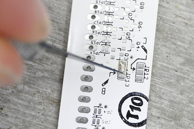
- PWM LED Disconnect - If you don’t want the LEDs to illuminate when using PWM from the C.H.I.P. Pro pins, cut this trace.
- MIC1 Disconnect - Cut this trace to disconnect the onboard microphone and enable the MIC1 pin on C.H.I.P. Pro.
- Enable Sleeve for MIC1 IN - Solder over these pads to use the sleeve (“S” of the TRRS) of the 1/8" audio jack.
- HP (headphone) Ground Select - Cut-and-solder these pads to change the grounding for the headphone jack. Cut between the pads with the line, then solder between the other two pads to use HPCOM instead of GND.
- Battery Disconnect - If you want to add a switch for a battery, you’ll need to cut this trace, then solder a switch into the through-holes provided.
- USB1 Host Power Select - Cut-and-solder to power the USB A (host) jack from the barrel jack (wall power) instead of the default power from the USB Micro.
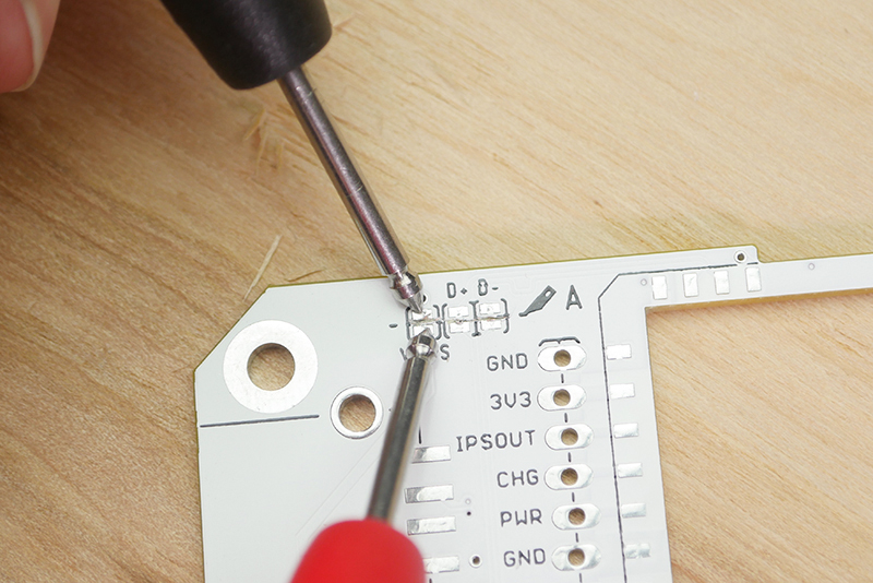
How to Cut
Here’s what you need to know about modifying and repairing the traces on the Dev Kit to experiment and test different configurations.
Cut
To get the job done you need to grab an X-acto knife or another small, sharp blade. The goal is to cut the trace connecting the two solder pads while NOT cutting anything else. The area to cut is very small so if you happen to own a pair of magnifying eye glasses now is the time to use them! To help stay in one place and not accidentally run the blade over another trace think of the cutting action as more of a digging one.
When you feel like you may have successfully cut through test the connection with your multimeter to confirm the disconnect.
Cut-and-Solder
Some of these require both a trace cut and a solder bridge. For example, the MIC1 power has three pads. Cut between two of the pads, and bridge two with solder.
Revert and Repair
Once you cut a trace it can be reverted to the original behavior. To replace the jumper solder a small piece of wire across all the contacts you wish to reconnect, or, if you are nimble, bridge the contacts with a solder blob.
If you need some reminding, circuit paths that came as default are indicated with a silkscreened bar under the originally connected pads.