

What’s a DIP?
DIPs are accessory boards that give new capabilities to C.H.I.P. DIPs come in many flavors, like official Next Thing Co. HDMI and VGA DIPs that give C.H.I.P. higher resolution video output to community DIPs that add more USB ports, control motors, or blink LEDs. C.H.I.P.s (with the proper software) automatically recognize when a DIP is attached and act accordingly.
Here you’ll find specs and instructions for the official Next Thing Co. HDMI and VGA DIPs as well as tips and tricks to get you started making your own.
Requirements
To properly recognize official NTC DIPs, C.H.I.P.s will need to update to at least Debian with Linux kernel 4.4. For a quick start on how to update your C.H.I.P., head to getchip.com/update. Full documentation exists in the Update C.H.I.P. to Linux kernel 4.4 section
Attaching DIPs
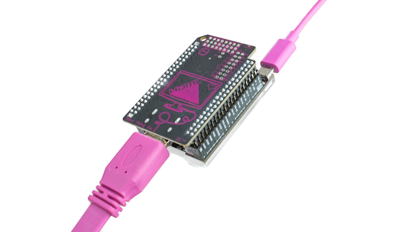
Here’s how you connect a DIP to C.H.I.P.
Orient the USB connector opposite the video connector.
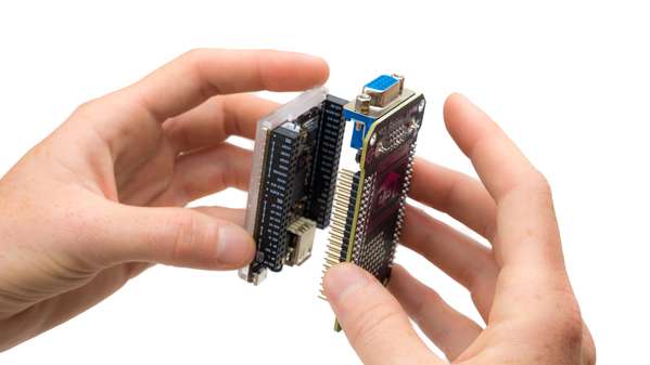
Align the pins to C.H.I.P.'s headers and gently press with even force until…
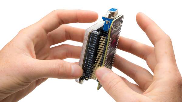
…the two pieces are joined. Tasty!
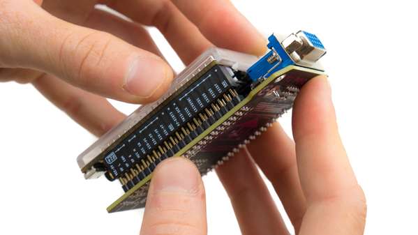
Disconnect the DIP
With great care! It’s important to pull with an even force to separate the DIP from the CHIP. It helps to gradually work the DIP away from the pin header at each side. When you can see a slight and even amount of exposed DIP pins on all sides, then you can grip the C.H.I.P. and DIP in the middle and pull them apart evenly. You do not want bent header pins on your DIP! We’ve found that the IC Extractor is an excellent companion if you want to frequently remove DIPs.
HDMI DIP
Intro
The HDMI DIP allows C.H.I.P. to connect to a monitor or television via an HDMI cable at a maximum resolution of 1920 by 1080 at 30Hz (a.k.a, 1080p). This DIP only provides a video signal over the HDMI cable: there is no audio encoded with it.
The HDMI DIP makes C.H.I.P. even better for traditional uses like presentations, classrooms, and games, and makes amazing things like large-scale installations, magic mirrors, and urban projection.
Parts and Pieces
What’s in the Bag?
There is one HDMI DIP in the electrostatic bag, packaged with protective foam. HDMI cables and C.H.I.P.s are sold separately at getchip.com
Pictures
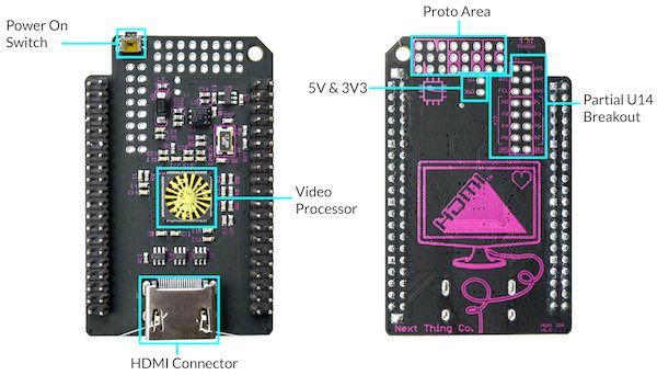
- Power switch: We added this is located on the top edge of the PCB, as it is close to impossible to access it.
- Prototyping area - There is “Proto board” on the PCB itself. This is convenient if you would like to add a small circuit to your DIP, without having to add another board.
- U14 partial breakout - This makes it easy to access the GPIO, UART, audio, and ground pins.
- Volts - 5V & 3V voltages are available below the NTC proto area.
- HDMI connector - A standard HDMI connector is used to send your video to a monitor, and is located at the bottom of the PCB.
- The Video Processor is the brains of the HDMI DIP. It takes the video from the LCD_Dx pins.
Requirements
- C.H.I.P. with C.H.I.P. OS 1.1 with Debian and Linux 4.4 kernel
- HDMI display
- HDMI cable
- 2A+ power adapter and micro USB cable
If you don’t have Debian with Linux kernel 4.4, or if you are unsure, follow this guide.
Use It
The HDMI DIP is extremely easy to use. Once you have your C.H.I.P. OS updated, it’s really as simple as attaching the DIP to your C.H.I.P, plugging in an HDMI monitor, plugging into your power supply and booting up C.H.I.P. But, for posterity’s sake, here’s all the details.
- Connect DIP to C.H.I.P.
- Connect cable to DIP and monitor
- Connect C.H.I.P. to power supply
- Power up C.H.I.P.
Once C.H.I.P has power, you’ll start seeing output on your monitor. Don’t try to power C.H.I.P. with the HDMI DIP from your computer’s USB power supply. There simply isn’t enough power!
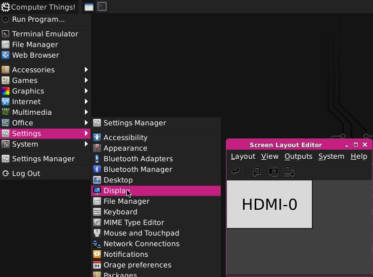
Once C.H.I.P is booted, you may want to change the resolution. You can do this with the control panel found in the Computer Things menu, going to Settings/Display
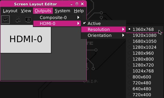
In the Display control panel, you can select a resolution in the Outputs menu:
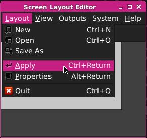
After you select a resolution, you’ll need to “Apply” it:
If you like using commandline in the terminal, you can change resolutions with xrandr, such as
xrandr -s 1280x720
Know it
Supported Resolutions
We cannot provide an exhaustive list of all resolutions, since this can depend on the attached monitor, but here are some observed resolutions:
- 1360x768
- 1920x1080
- 1680x1050
- 1280x1024
- 1280x960
- 1280x800
- 1280x720
- 1024x768
- 800x600
- 720x480
- 640x480
- 720x400
Video Only
HDMI DIP only does video - it does not carry an audio signal. However, the audio connectors on the 3.5mm TRRS jack and header pins still output stereo audio normally.
How to Disconnect the DIP
With great care! It’s important to pull with an even force to separate the DIP from the CHIP. You do not want bent header pins on your DIP! We’ve found that the IC Extractor is an excellent companion if you want to frequently remove DIPs.
Hack It
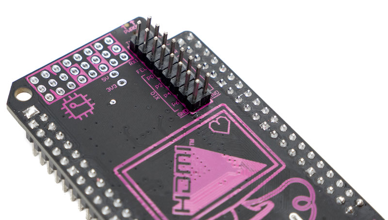
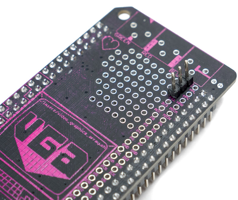
The HDMI DIP is hackable. There are breakouts for the headers and a small proto-board area so you can add some simple circuits. One example is adding a pin header so you can access C.H.I.P.'s UART bus. This image shows an HDMI DIP with the added pin header soldered in place:
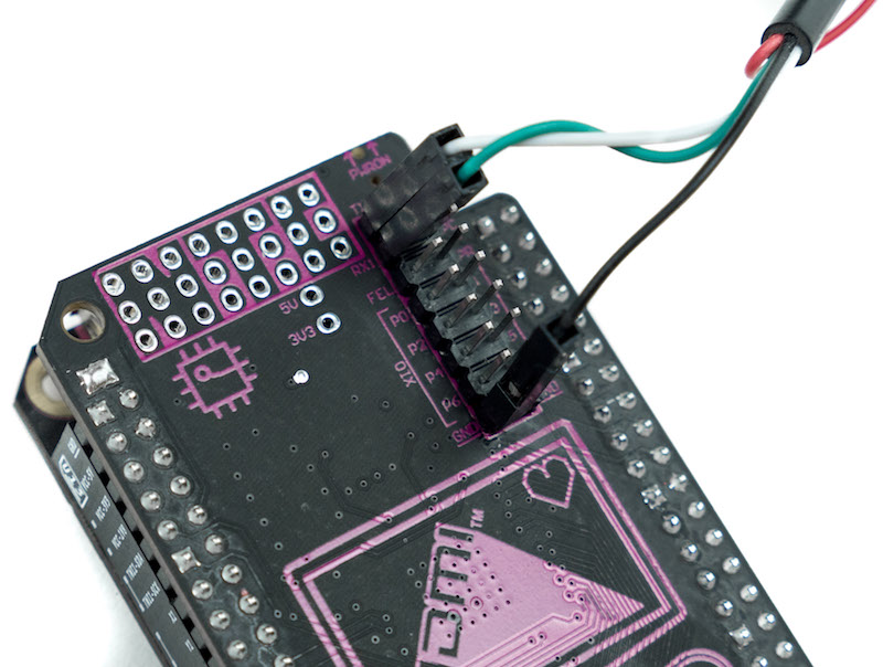
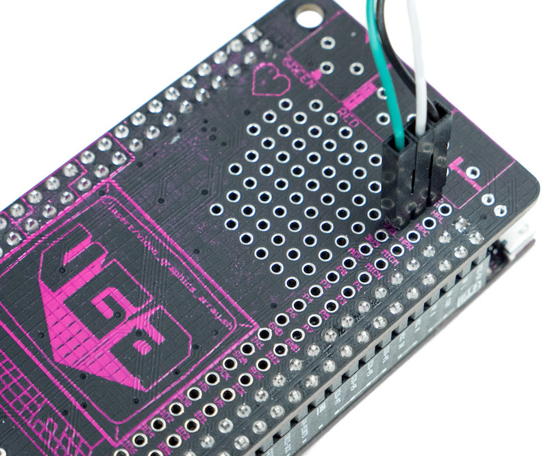
and the receive, transmit, and ground wires of a USB-UART cable connecting CHIP to a computer’s serial bus:
Open Source
The HDMI DIP is open source. Design files are in our github repo.
VGA DIP
Intro
The VGA DIP allows C.H.I.P. to connect to a monitor via a standard 15-pin VGA cable at a maximum output resolution of 1600 by 900 at 60 Hz. Unlike the 16:9 ratio of HDMI, the VGA DIP usually outputs in a 4:3 aspect ratio.
Parts and Pieces
What’s in the Bag
There is one VGA DIP in the electrostatic bag, packaged with protective foam. VGA cables and C.H.I.P.s are sold separately at getchip.com
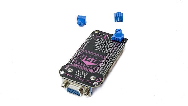
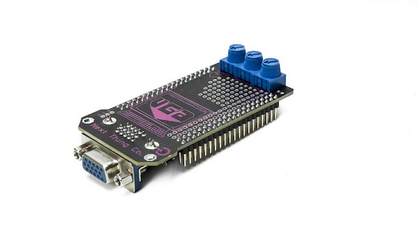
Pictures
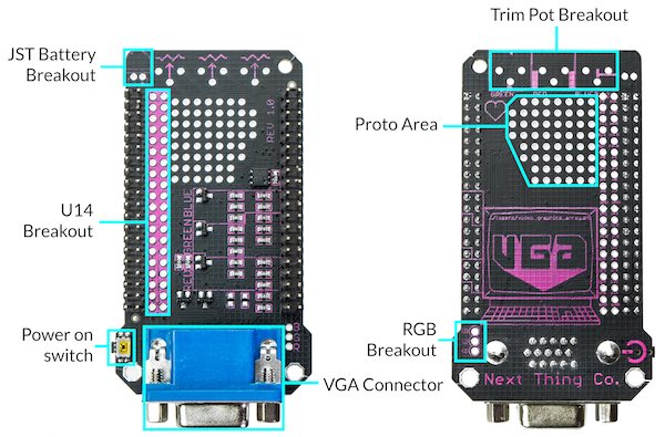
- RGB breakouts - RGB breakouts can be found at the edge of the VGA connector on the left side. These are available if you ever want to add cool effects, or to “bend” your VGA DIP
- Trim-pot breakouts (RGB) - There are three footprints for1 0K trimpots. These can be installed with only a few solder joints, and can create a really awesome visual effects like saturating colors.
- U14 breakouts - The U14 header breakout is directly to the left of U14. This is important if you would like to access FEL, UART, XIO, CSID, audio, etc. The name of each pin is labeled above the corresponding pad.
- JST connector breakout - A JST connector footprint is available to be populated on VGA DIP. Because the VGA connector is really close to the existing JST battery connector, it makes it difficult to plug/unplug with the VGA DIP installed. Note: DO NOT INSTALL TWO BATTERIES INTO C.H.I.P. THIS WILL DAMAGE YOUR C.H.I.P.
- Prototyping area - There is “Proto board” on the PCB itself. This is convenient if you would like to add a small circuit to your VGA DIP, without having to add another board.
- VGA connector - This is a standard female DB-15 VGA connector to carry the video signal to a VGA monitor.
- Power switch - A Power switch has been added to the VGA DIP. It is close to impossible to access the Power On Switch on C.H.I.P with the VGA DIP installed, so we added a second Power On Switch. This is located on the right side of the PCB, and is accompanied by a “Power On” symbol.
Requirements
- C.H.I.P. with C.H.I.P. OS 1.1 with Debian with Linux kernel 4.4
- VGA display
- 15-pin VGA cable (we recommend a cable with Ferrite beads)
- 2A+ power adapter and micro USB cable
If you don’t have Debian with 4.4 kernel, or if you are unsure, follow this guide
Use It
The VGA DIP is extremely easy to use. Once you have your C.H.I.P. OS updated, it’s really as simple as attaching the DIP to your C.H.I.P, adding power to C.H.I.P., plugging in a VGA monitor, and booting up C.H.I.P. But, for posterity’s sake, here’s all the details.
- Update C.H.I.P. OS
- Connect DIP to C.H.I.P.
- Connect cable to DIP and monitor
- Connect C.H.I.P. to power supply
- Power up C.H.I.P.
Once C.H.I.P has power, you’ll start seeing output on your monitor. Once C.H.I.P is booted, you may want to change the resolution. You can do this with the control panel found in the Computer Things menu, going to Settings/Display
In the Display control panel, you can select a resolution in the Outputs menu:
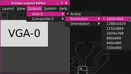
After you select a resolution, you’ll need to “Apply” it:
If you like using commandline in the terminal, you can change resolutions with xrandr, such as
xrandr -s 1024x768
Know It
Supported Resolutions
We cannot provide an exhaustive list of all resolutions, since this can depend on the attached monitor, but here are some observed resolutions:
- 1600x900
- 1280x1024
- 1152x864
- 1024x768
- 800x600
- 640x480
- 720x400
Hack It
The VGA DIP is hackable. There are breakouts for the headers and a small proto-board area so you can add some simple circuits. There’s also access to the RGB signals for extra colorful fun! Here are a couple example hacks that bring joy and utility to your VGA DIP.
RGB Trim Pots
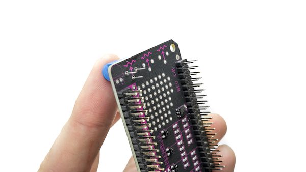
Heat up your soldering iron, the VGA DIP is hackable. You may have noticed the pads suitably spaced for 10K trim pots, and the RGB breakouts. Here’s a photo guide to soldering up some trim pots so you can manually adjust the individual red, green, and blue levels in the image. You can find these pots at vendors such as digikey and mouser
Trim pots are able to go in one way on TOP of the PCB for accessibility.
Trim pots are sized and spaced for a precise alignment.
Here we see that there is only one way for the pots to go on the TOP side.
Solder the leads and trim them like so.
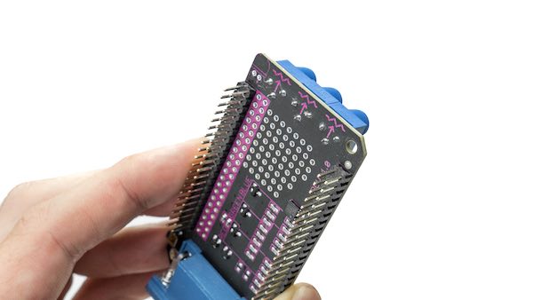
Time to start Bending Colors!!!
UART Connection
Another example is adding a pin header so you can access C.H.I.P.'s UART bus. This image shows an VGA DIP with the added pin header soldered in place:
and the receive, transmit, and ground wires of a USB-UART cable connecting CHIP to a computer’s serial bus:
Open Source
VGA DIP is open source. Design files are in our github repo.
# Update C.H.I.P to Linux kernel 4.4
DIPs require that C.H.I.P. is running the Debian 4.4 Linux kernel. Here’s a detailed guide to determining if you need to update and how to update using our web flasher.
Determine C.H.I.P.’s Kernel Version
To determine if you need to upgrade your C.H.I.P.’s kernel, connect a keyboard, mouse, and display to C.H.I.P., then power up CHIP.
Then, open the Terminal application (from the drop-down menu at the top, left corner of the Desktop.
Once the applications loads, type uname -a. This outputs information about your system software version.
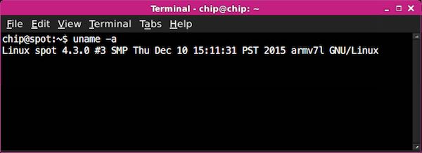
Look for a number in appended with -ntc, for example 4.3.0 or 4.4.0. This number is the kernel version running on your C.H.I.P. If the number is 4.4.0 or greater, you don’t need to upgrade your kernel version. Most likely, your number is 4.3.0, keep reading: you need to upgrade your kernel.
Back-up C.H.I.P.’s Data
Backup any important data on your C.H.I.P. before you upgrade your system. Upgrading will overwrite all of the C.H.I.P. storage. You can backup your user directory with a simple command in the Terminal emulator:
tar cfpzv homebackup.tar.gz /home/chip
You can transfer that tar file to another computer or cloud service from C.H.I.P. There’s more to learn in this detailed guide.
If you have installed a lot of packages with Synaptic or apt, and would like to be able to be able to easily re-install those packages, there’s some good guides and suggestions on the web.
Upgrade the Kernel with the C.H.I.P. Flasher
Using the Chrome or Chromium web browser, visit flash.getchip.com and follow the on-screen instructions. When the flasher presents you with different OS images to choose from, click on “CHIP OS 1.1” to select it.
When flashing is complete, follow the instructions for using your DIP.
DIP Specifications
As you might imagine, a DIP could be almost anything that plugs into C.H.I.P. While our VGA and HDMI DIPs provide very specific capabilities, a less obvious DIP example is the PocketC.H.I.P: its touchscreen, case, keyboard, and extensive circuit board may seem to be product distinct from C.H.I.P, but it is in fact, merely a DIP that attaches to C.H.I.P. and identifies itself to the operating system. Since function isn’t really limited by our specification, it’s important to know that to call something that attaches to C.H.I.P. a “DIP”, it needs to comply with the C.H.I.P. DIP specifications described in this document.
Form Factor
There is no form factor for DIPs - go and surprise us! A DIP could host just a tiny button, or be a 30-foot robot that hands out nutritious snacks to small children. However, there are considerations for certain parts that will make it easier to connect a C.H.I.P. with a DIP.
DIP Identification
C.H.I.P. needs to know which extension board is attached in order to configure Linux accordingly. To do this, C.H.I.P. checks for a 1wire EEPROM at boot time.
If a 1wire EEPROM is detected, its data is read, and if C.H.I.P. recognizes a supported DIP, it automatically sets up the software accordingly (using a device tree overlay).
The 1wire EEPROM needs to be connected to the LCD_D2 pin on pin header U13 and should be able to store a least 122 bytes (see data-format below). The DS2431 is a common EEPROM part that works well for this.
This readable EEPROM is actually the only requirement for an extension board to comply with the DIP specification.
Data Format
The data is structured as follows:
| Offset | Length | Name | Description |
|---|---|---|---|
| 0x00 | 4 | MAGIC | Header to identify a DIP, must be ‘C’,’H’,’I’,’P’ |
| 0x04 | 1 | VERSION | Version of the data format |
| 0x05 | 4 | VENDOR ID | 32-bit vendor ID, must be unique |
| 0x09 | 2 | PRODUCT ID | 16-bit product ID, vendor manages product ids |
| 0x0B | 1 | PRODUCT VERSION | Product version, managed by vendor |
| 0x0C | 32 | VENDOR NAME | Vendor name as human readable ASCII string |
| 0x2C | 32 | PRODUCT STRING | Product name as human readable ASCII string |
| 0x4C | 20 | RESERVED | space reserved for future updates |
| 0x60 | 16 | USER DATA | Random data, e.g. a MAC address for an ethernet DIP |
Vendor ID and Product ID
Each DIP must have a unique combination of vendor and product id for C.H.I.P. to recognize it. We have a very simple, open system for makers to register vendor IDs self-contained in a github repository. Even if you don’t want to sell it, it’s worth getting an ID, to prevent the chance of your DIP confusing C.H.I.P. in the future.
Reserved VIDs
There are some vendor IDs that are reserved.
- Next Thing Co uses 0x009d011a as VID.
- VIDs 0x00000000 - 0x0000000f reserved for prototyping.
Existing Products
So far, these official DIPs exist:
- PocketC.H.I.P. (VID=0x009d011a, PID=0x00000001)
- VGA DIP (VID=0x009d011a, PID=0x00000002)
- HDMI DIP (VID=0x0090d011a, PID=0x00000003)
How does C.H.I.P. handle device setup and drivers?
DIP makers can provide their own drivers and device tree overlays as .deb package.
A registered vendor id does not imply the device tree overlay will be included in the official C.H.I.P. firmware.
The DIP Maker Guide provides a git repository with sample code, a script for compiling device trees, and a script for flashing EEPROM with data. Read more and get the repo here.
DIP Maker’s Guide
This guide provides the resources and instructions for making a Device Tree Overlay (DTO) for your DIP. The DTO provides information at boot-time that can automatically configure your C.H.I.P. with drivers and resources to make your DIP work as expected on startup.
Getting Started
Install git with sudo apt-get install git, then clone the DIP device tree overlay sources onto a Debian/Ubuntu computer or C.H.I.P.:
sudo apt-get update && sudo apt-get install git
git clone https://github.com/NextThingCo/CHIP-dt-overlays.git
This repository has some very useful directories and files for getting your DIP working with your C.H.I.P.:
- samples/ - some basic examples
- nextthingco/ - NTC DIP overlay examples
- fimware/ - example of a DTS that would compile to DTBO that would load with EEPROM
- tools/ - script that generates an eeprom file that can be used to auto-load a DTBO
- Makefile - run
maketo compile your device tree overlays in/samplesand/firmwareinto device tree blob overlay files.
You will need to make sure you have Linux kernel version 4.4 or later. Read more about this in the update section
When do you need a Device Tree Overlay?
The advantage to creating a Device Tree Overlay file is that it will automatically configure C.H.I.P. with the correct settings when C.H.I.P. is booted with the DIP attached. If your DIP merely used the GPIO XIO pins, for example, it would work without any further configuration in the system device tree.
However, most of the pins accessed on the U13 and U14 jumpers represent some protocol for addressing different types of hardware, and how they need to behave usually depends on what hardware they are interacting with.
These types of hardware usually need a driver. They will need configuration by a Device Tree Overlay to let the system know how to present the hardware to software. The exceptions are devices simple enough to be driven by an application through the GPIO sysfs interface, /dev/i2c-* or /dev/spidev*. Even devices that work without configuration can be further refined for software when configured with an overlay.
The overlay will generally deal with the the bus used to connect to C.H.I.P. (i2c, 1wire, serial, etc) and the hardware added to that bus.
The settings needed for the chosen bus will be related to the specifications of the hardware on your DIP and the pins on the Allwinner R8, which are exhaustively documented in the R8 User Manual
The settings needed for the overlay for the components on the bus are usually provided in the vendor’s documents.
Bus Protocols
The following protocols can be enabled and configured with Device Tree Overlay files. Each protocol can be configured with a “fragment” in a DTO. Because some of these functions share pins, not all of these can be enabled at once. For example, if SPI2 is enabled, then it would not be possible to enable the CSI interface, since they share pins on U14.
| Device/Protocol | Target name |
|---|---|
| Two Wire Serial (I2C) | <&i2c0> or <&i2c1> or <&i2c2> |
| Touch Screen | <&rtp> |
| LCD display | multiple(+) |
| GPIO | <&pio> |
| GPIO Expander Pins | <&xio> |
| Pulse Width Modulation (PWM) | <&pwm> |
| Serial Peripheral Interface (SPI) | <&spi2> |
| CMOS (Camera) Sensor Interface (CSI) | no driver yet |
| API Interrupt | <&pio> |
(+) several device and bus targets are used for an LCD display. See the PocketC.H.I.P. overlay in the DDK repo at nextthingco/dip-pocket.dts
These protocols are enabled on C.H.I.P. by default. It is extremely unlikely your DIP would benefit from additional configuration with a DTO:
- One Wire Serial
- UART Serial
- Audio I/O
- Composite Video Output
- USB OTG
- USB
- Bluetooth
- Wifi
- USB Power
- Battery power
- Low Res Analog Digital Converter (not yet enabled, but will be by default)
Development by Example
In this section, we’ll use a very simple DIP that hosts a button, an LED, and a temperature sensor (Melexis MLX90614) and controls it via I2C on C.H.I.P.'s TWI1 data and clock lines. These correspond to Pins 9 and 11 on pin header U13. The R8 data sheet refers to these as PB15 and PB16.
Make your Add-on Device
In some ways, creating your overlay is interlaced with the process of development. As you prototype your DIP, you’ll need to adjust your overlay as you change parts, add components, or test different hardware.
Fortunately, our example is very basic: the temperature sensor is the only component that requires a device tree overlay, and the driver for that component already exists. Of course, we’ll also need to put the EEPROM on it which will be used to identify the device when C.H.I.P. boots.
Enable devices and components with DTS
Once you have a setup for your DIP, you’ll need to create an overlay that will let you test your hardware with software. Here’s an overlay that enables i2c1 on C.H.I.P. and configures the temperature sensor.
The bindings for this sensor can be found in the devicetree bindings directory:
/*
 * Peter Nyboer
 * [email protected]
 * DTO for Melixis MLX90614 IR temperature sensor 3.3V
 * http://melexis.com/Infrared-Thermometer-Sensors/Infrared-Thermometer-Sensors/MLX90614-615.aspx
 */

/dts-v1/;
/plugin/;

/ {
	compatible = "nextthing,chip", "allwinner,sun5i-r8";

	/*
	 * Make sure the i2c index is right
	 */
	fragment@0 {
		target-path = "/aliases";

		__overlay__ {
			/* Path to the i2c1 controller node */
			i2c1 = "/soc@01c00000/i2c@01c2b000";
		};
	};

	/*
	 * Device Tree Overlay to enable i2c1 and add an mlx temp sensor
	 */
	fragment@1 {
		target = <&i2c1>; // on U13

		__overlay__ {
			//configuration information for Allwinnerdevice protocol target.

			#address-cells = <1>;
			#size-cells = <0>;
			pinctrl-names = "default";
			pinctrl-0 = <&i2c1_pins_a>;
			status = "okay";


			mlx90614: mlx90614@5a { //using default addr
				compatible = "melexis,mlx90614";
				reg = <0x5a>;
				//wakeup-gpios = <&gpio0 2 GPIO_ACTIVE_HIGH>;
			};

		};
	};
};
Notice that the wakeup-gpios option is commented out - this makes testing simpler since this will not enable any power management features on the MLX90614.
Make a DTBO - Device Tree Overlay Blob
Think it’s right? Now it’s time to compile and test it. Unfortunately, the device tree compiler patches needed to support the overlays have not been merged into the mainline dtc code yet, so you need a patched version of the compiler. Lucky for you, we have a patched version available. The first line installs some dependencies that the dtc Makefile depends on.
sudo apt-get install flex bison
git clone https://github.com/nextthingco/dtc
cd dtc
make
sudo  make install PREFIX=/usr
The easy way to compile is to put your .dts file in the “samples/” directory of the CHIP-dt-overlays directory, then, from the root of this repository, just run make. This produces a .dtbo (device tree blob) file in the “samples/” directory with the .dts file.
The Makefile is designed to look in the “samples/” and “firmware/” directories for .dts files and compile them to .dtbo files using this command:
dtc -I dts -O dtb -o <output file>.dtbo <input file>.dts -@
You may find this useful if you are just want to compile a dts file in-place. More information on the device tree compiler can be found in the ubuntu manpages site
Manually Load your Overlay
Once you have compiled your device tree blob, you will need to add the overlay to the existing device tree. First, make sure configfs is mounted:
sudo mount -t configfs none /sys/kernel/config
then make a place for the overlay and catenate your blob:
sudo mkdir -p /sys/kernel/config/device-tree/overlays/DIPexample
su -c 'cat irtempi2c.dtbo > /sys/kernel/config/device-tree/overlays/DIPexample/dtbo'
If you want to remove it later on, simply remove the directory you
created:
sudo rmdir /sys/kernel/config/device-tree/overlays/DIPexample/
Confirm Overlay Loaded
Before you started this procedure, you would have seen two i2c devices where ls /dev/i2c* would output /dev/i2c-0 /dev/i2c-2. After the overlay is applied, the output from that ls will show the new i2c device: /dev/i2c-0 /dev/i2c-1 /dev/i2c-2
If you want to find the device in sysfs, you can ls /sys/bus/i2c/devices/ and see a device 1-005a. The “1” refers to the new i2c bus i2c-1 and “005a” refers to the address of the device (“reg” in the dts file). (You’ll also see 0-0034 and 2-0038 which are the AXP209 power management and the GPIO expander for the XIO pins that are connected to i2c0 and i2c2, respectively). You can probe even deeper with ls /sys/bus/i2c/devices/1-005a to see what is exposed to the system for the IR temperature sensor.
You can also use sudo i2cdetect -y 1 to see a table of all devices on i2c-1. That command will probe the i2c-1 bus for devices and see if any replies.
Overlays that have been manually loaded like this will not be available on reboot. You will need to load the overlay again if you reboot.
Test board and iterate
Now that C.H.I.P. knows about the new devices, it’s time to start programming and controlling the elements on the DIP.
Make it a DIP
Once you have a final product, you can place the EEPROM chip on the 1wire bus, and flash the EEPROM to make C.H.I.P. automatically configure for your DIP. The EEPROM is the secret sauce that turns a “PCB with some stuff on it” into a flavorful DIP that pairs perfectly with your C.H.I.P.
Flash EEPROM
With your finished board, you are now ready to flash the EEPROM with your unique data. The “tools/” directory in the DDK has a simple python script that can be used to generate a file that can be written to the hardware.
Let’s make up some values that you’ll need to write to the EEPROM.
- vendor ID (vid) = 0x16 (22) [32 bit]
- product ID (pid) = 0x44 (68) [16 bit]
- vendor = RadCo [32 characters]
- product = SuperT [32 characters]
- product-version = 1 [8 bit]
From the “tools/” directory, run
python dip-header-generator.py SuperTEEPROM.img --vid 22 --pid 68 --vendor 'RadCo' --product 'SuperT' --product-version 1
to generate an EEPROM file “SuperTEEPROM.img”.
You’ll find the EEPROM device in the sysfs file system:
ls /sys/bus/w1/devices/2*/eeprom
Once you know the UUID (name) of the directory (e.g. “2d-0000132785ea/”), you can write the data to the eeprom with:
su -c 'cat SuperTEEPROM.img > /sys/bus/w1/devices/2d-(UUID)/eeprom'
Verify EEPROM
For personal assurances, you may want to verify that the EEPROM has the correct data on it. Use this command to print the data in (hexadecimal format) to your terminal:
cat /sys/bus/w1/devices/2*/eeprom |hexdump -C
You can also use a lowercase -c option to print the data in character format, which is useful for viewing the vendor strings.
Boot with DIP in place (read EEPROM)
Now that you have a functioning device tree blob and EEPROM populated with data unique to your product, you’ll need to name your blob with a special name using your (hex) vendor ID and product id:
dip-16-44.dtbo
then
sudo mkdir -p /lib/firmware/nextthingco/chip && sudo cp dip-16-44.dtbo /lib/firmware/nextthingco/chip
to put it in /lib/firmware/nextthingco/chip/ to ensure the overlay is loaded on EEPROM detection.
You may also need to make sure that the w1_ds2431 module loads on boot so the EEPROM module can be found and read. You simply need to modify the configuration file with a text editor sudo nano /etc/modules.d/modules.conf and add this line to the end: w1_ds2431
Use DIP with software
Now you are ready to use your DIP with software. How you control your DIP with C.H.I.P. is really up to you. This procedure simply makes the DIP’s parts available to the operating system for further control.
The Device Tree Overlay format
A template for a basic DTO:
/*
 * Copyright or left statement
 * Author name(s) and and contact
 * License Information
 */

/dts-v1/;
/plugin/;

/ {
	compatible = "nextthing,chip", "allwinner,sun5i-r8";

	/*
	 * Fragment description
	 */
	fragment@1 {
		target = <targetname>; // example: <&spi2>

		__overlay__ {
			//configuration information for Allwinner device target.

			controller: controller@0{
				//optional controller configuration and bindings to the hardware C.H.I.P. talks to on the DIP, usually needed for bu
			};
		};
	};
};
The device tree is composed of nodes, where each node configures a device that Linux must relate to a driver and know what interface to present to the system.
The top of the “overlay” node describes settings that are relevant to the C.H.I.P.'s target device, such as <&i2c1>, <&spi2>, <&pwm>. Example settings and documentation for these take some detective work in the C.H.I.P.-linux repo, for example device trees for sun5i and sun5i-r8
Documentation for the settings that will go in the controller sub-node depends on the device and what is built on the DIP. Much of this type of information can be found in the bindings directory of the C.H.I.P.-linux repo. You may also need to refer to the hardware’s data sheet to get some data for the node.
We realize this is fairly unspecific instruction; given the number of mainline Linux driver, devices and possible combinations, it’s difficult to provide much more than guidance.
You may find these resources for other hardware useful:
The Device Tree and U-Boot
Some DIPs require the device tree to load with U-Boot, in order to make the devices available earlier in the startup process. The VGA, HDMI, and PocketC.H.I.P. overlay blobs are three examples of DIPs that require this behavior, because the display needs to be known to C.H.I.P. as early as possible. This requires a different overlay loading procedure, which is definitely the exception rather than the norm.
Modify U-Boot
Connect C.H.I.P. to a monitor or use a USB UART cable so you can stop C.H.I.P. from fully booting. Hit any key in the first 2 seconds, then type these commands:
setenv dip_addr_r 0x43400000
setenv dip_overlay_dir /lib/firmware/nexttching/chip/early/
setenv dip_overlay_cmd 'ubifsload $dip_addr_r $dip_overlay_dir/$dip_overlay_name'
This process will soon be unneeded, as these commands will be rolled into U-Boot.