

Get Started With C.H.I.P. Pro
The C.H.I.P. Pro System-on-Module (SOM) is designed to get you making great products instead of re-inventing computers. It’s a low-cost, high-capability module that lets you focus on fast iterations of brilliant ideas that will be ready to manufacture.
To get the most out of developing and designing for C.H.I.P. Pro we recommend prototyping with the C.H.I.P. Pro Development Kit.
This document provides technical details that will make integrating C.H.I.P. Pro module into your designs a breeze, along with technical specifications and basic guides to get you connected and working with software on C.H.I.P. Pro.
At a Glance C.H.I.P. Pro’s Features:
- 512MB of NAND storage
- 2.4GHz WiFi and Bluetooth connectivity
- Onboard power and battery charging management
- Pins for popular I/O busses
- 2x USB Port (1x USB 2.0 Host, 1x OTG)
- Security and flexibility of mainline Linux
- Breadboard and SMT compatible
- Dimensions: 45mm x 30mm
Comprehensive audio handling includes:
- 24-bit ADC/DAC for stereo audio in and out
- one-wire audio digital out
- I2S digital audio for interfacing with industry standard audio codecs.
To learn more, go to our Specification section.
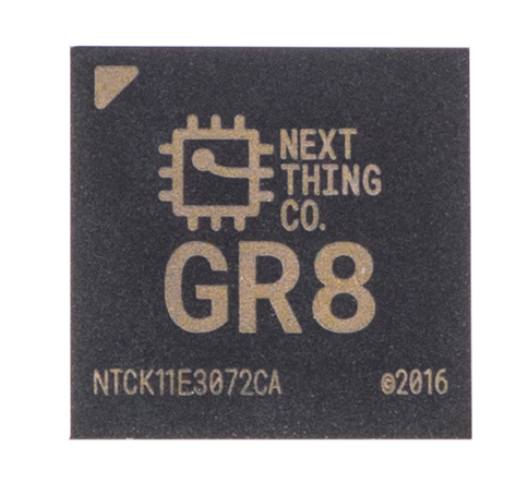
GR8 SiP
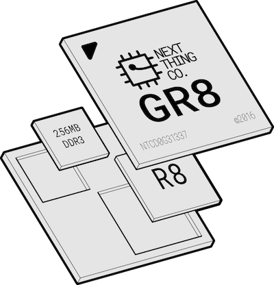
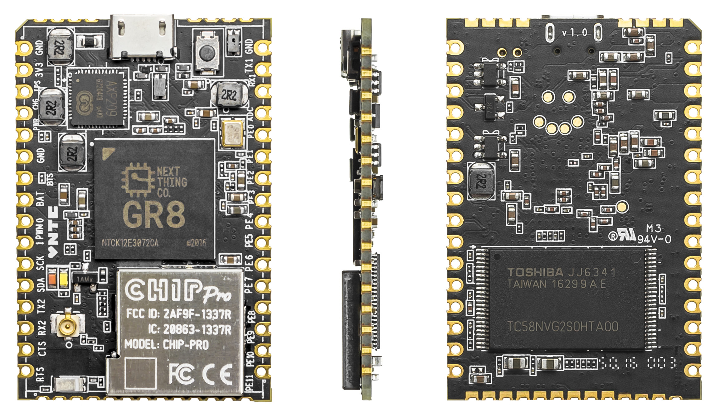
C.H.I.P. Pro is powered by Next Thing Co’s GR8 SiP (System in Package). GR8 features a 1GHz Allwinner R8 ARMv7 Cortex-A8 processor with NEON SIMD extensions and a Mali-400 GPU. 256MB of Nanya DDR3 SDRAM is combined with the R8 processor into a 14mm x 14mm, 0.8mm pitch 252 ball FBGA package.
In addition to the Mali-400 graphic engine that supports OpenGL ES 1.0 and 2.0. GR8 includes a video engine for encoding and decoding codecs such as VP6/8, AVS, H.264, H.263, MPEG-1/2/4 and a display engine for a hardware cursor, alpha blending, and anti-flicker.
More information about the GR8 SiP can be found in the GR8 data sheet.
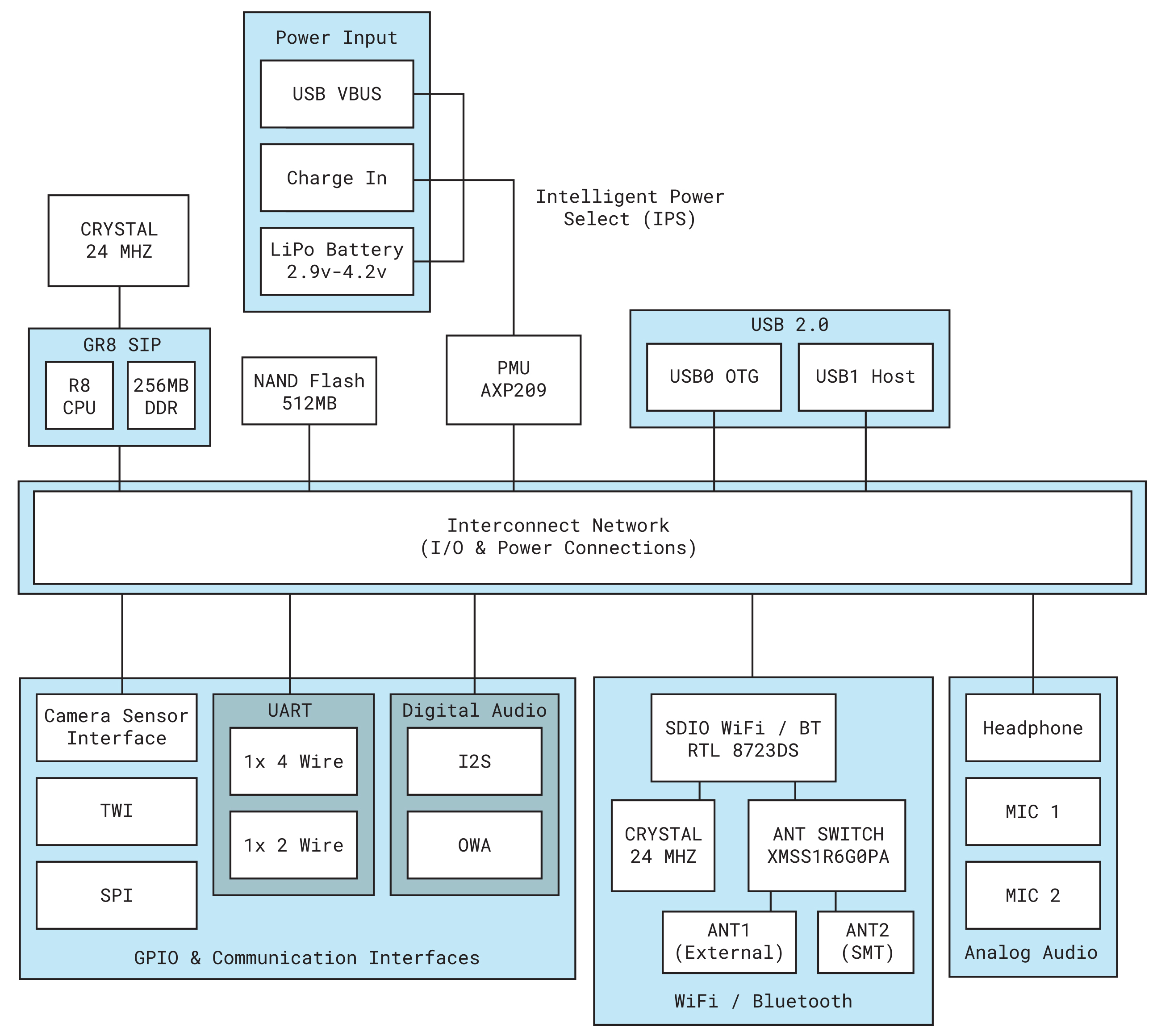
Block Diagram
Connect and Control
Flash an Operating System
Like its older sibling C.H.I.P., C.H.I.P. Pro’s GR8 SiP runs mainline Linux by default. This provides security, flexibility, robust tools, and open-source options. In the interest of power consumption and storage space, we have two OS options to best fit your needs:
Debian is a classic amongst embedded Linux board users for rapid prototyping. It offers a full package manager and loads of precompiled software and familiar command-line tools.
Buildroot is simple and stripped down making it efficient and ideal for permanent deployment and high-reliability embedded systems.
C.H.I.P. Pro has 512MB of high-reliability SLC NAND storage onboard for holding the core operating system and a limited amount of user and program data. While the storage is faster and more reliable it has less capacity. Because of this, it’s a good idea to know how much storage software will take before flashing and installing. Where needed, additional high-speed storage can be added through C.H.I.P. Pro’s SDIO bus.
Grab these items to flash C.H.I.P. Pro:
- C.H.I.P. Pro
- USB A to Micro-USB B cable
- Separate computer with Chrome or Chromium browser and an internet connection.
Flashing Process
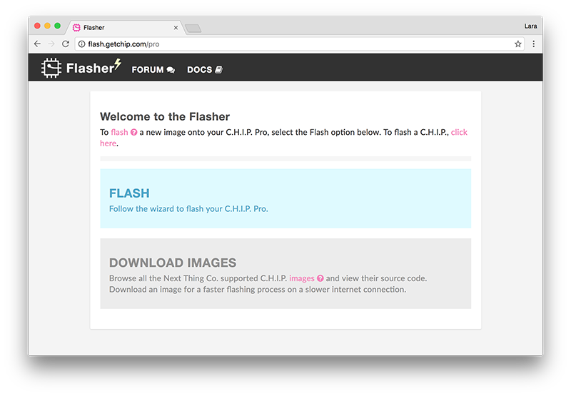
Head over to the web flasher at flash.getchip.com/pro. If it’s your first time flashing, when you arrive you will be asked to install the NTC Flasher Chrome Extension.
After installing the extension, the main page will give you the option to either download an image or follow the wizard to flash C.H.I.P. Pro.
Download an image to look at the source code or store and flash a board with it when you see an option for choosing an image from your computer.
Click FLASH to flash C.H.I.P. Pro.
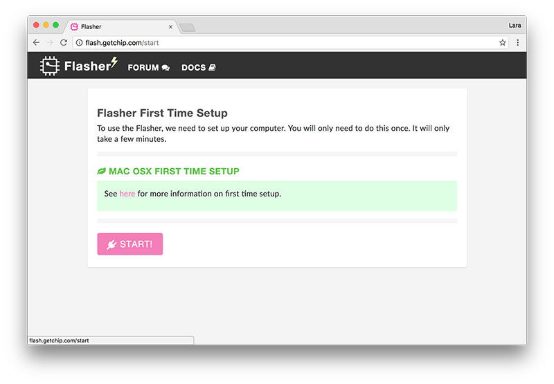
You will then arrive at the “Flasher First Time Setup” page which will have setup instructions specific to your computer’s operating system. Follow along in the browser or below.
-
Linux-specific
- A Debian-based Linux computer requires creating a set of udev rules to communicate with your C.H.I.P. Pro. Paste the following into a terminal window.
sudo usermod -a -G dialout ${USER}
sudo usermod -a -G plugdev ${USER}

# Create udev rules
echo -e 'SUBSYSTEM=="usb", ATTRS{idVendor}=="1f3a", ATTRS{idProduct}=="efe8", 		GROUP="plugdev", MODE="0660" SYMLINK+="usb-chip"
SUBSYSTEM=="usb", ATTRS{idVendor}=="18d1", ATTRS{idProduct}=="1010", GROUP="plugdev", 	MODE="0660" SYMLINK+="usb-chip-fastboot"
SUBSYSTEM=="usb", ATTRS{idVendor}=="1f3a", ATTRS{idProduct}=="1010", GROUP="plugdev", 	MODE="0660" SYMLINK+="usb-chip-fastboot"
SUBSYSTEM=="usb", ATTRS{idVendor}=="067b", ATTRS{idProduct}=="2303", GROUP="plugdev", 	MODE="0660" SYMLINK+="usb-serial-adapter"
' | sudo tee /etc/udev/rules.d/99-allwinner.rules

sudo udevadm control --reload-rules
Then logout and log back in.
For the curious:
-
${USER}: outputs your username
-
dialout: gives non-root access to serial connections
-
plugdev: allows non-root mounting with pmount
The udev rules then map the usb device to the groups. For more information, check the systems group page on debian.org.
-
Windows-specific
- To communicate to C.H.I.P. Pro from a Windows computer you must install drivers.
- Reboot after installing drivers on previous versions (<10) of Windows.
- During the fastboot process Windows may issue the warning “device not recognized”. Getting this warning during fastboot is normal and flashing should proceed.
-
MacOS specific
- Using USB3 ports can cause the flashing to fail. If you can, try using a USB2 port, not a USB3. If you find yourself with a modern Mac that only has USB3 ports, try using a USB2 hub in your USB3 port and plug C.H.I.P. Pro into that.
- OS X El Capitan has been known to have issue with the flashing process. If a new cable or USB2 hub does not work and you are able to, upgrade to macOS Sierra.
After you have setup your computer, press START!.
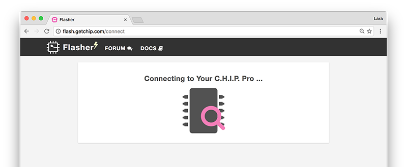
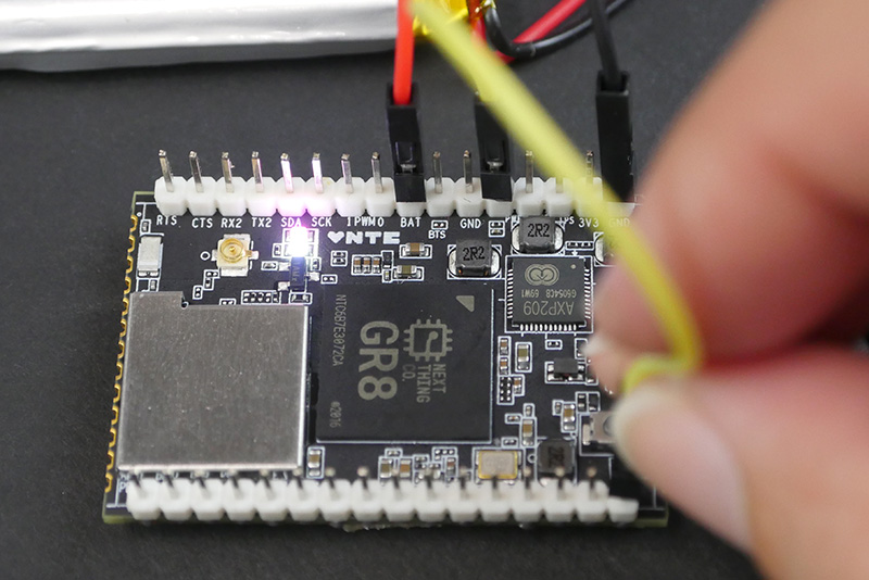
Plug the micro USB cable into the micro USB port on C.H.I.P. Pro. Hold down the FEL button (a pencil eraser works nicely) and with the other hand plug the USB cable into the computer. When the pink power and white status LEDs on C.H.I.P. Pro light up, you can release the FEL button.
The web flasher will search for and recognize C.H.I.P. Pro.
You will then be directed to the page with the example images. Hover over each image to see a description and click to see more details such as file size and kernel version. When you have chosen your adventure, click FLASH TO C.H.I.P. PRO.
[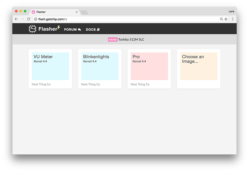 ] (images/imagesPage.jpg) ] (images/imagesPage.jpg) |
[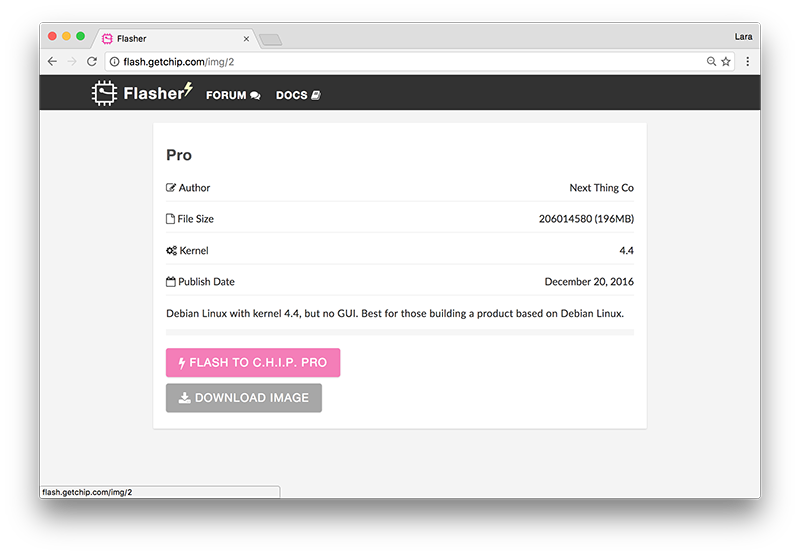 ] (images/imageDetail.png) ] (images/imageDetail.png) |
|---|---|
| Choose image | Click FLASH TO CHIP PRO |
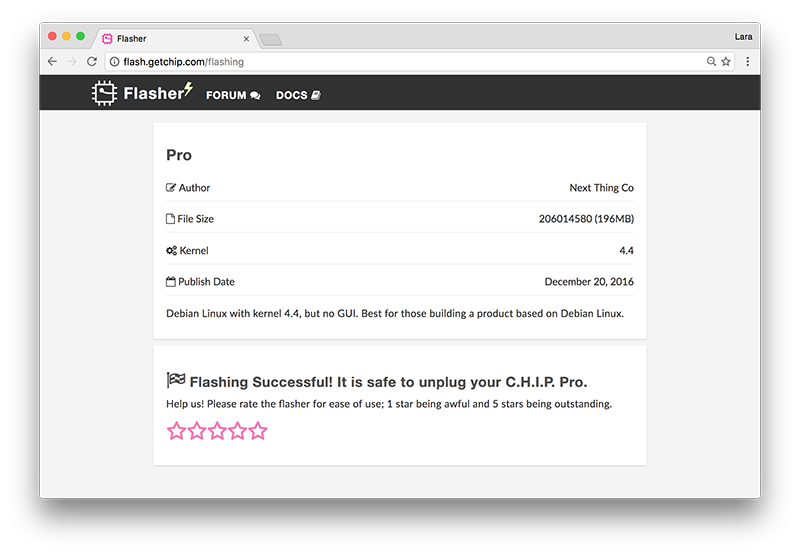
Watch the flashing process progress and leave the browser tab open in order for it to complete. You will be notified when C.H.I.P. Pro has been flashed successfully. You are then free to unplug the C.H.I.P. Pro or connect to it via serial.
If you are having problems with the flashing process follow the troubleshooting instructions given by the web flasher or check out the Web Flasher OS-Specific Issues troubleshooting section.
Examples
You can select an OS by flashing one of our examples using the web flasher flash.getchip.com/pro in Chrome or Chromium browser.
We have built examples based on Buildroot that implement features exposed on the CHIP Pro Dev Board such as its two MICs, and array of GPIOs. If you are building a circuit that incorporates mics and LEDs with a bare C.H.I.P. Pro you can start with these examples.
Blinkenlights (Buildroot)
Size: ~60MB
This Python based example provides easy-to-understand code with exciting results. Flash C.H.I.P. Pro with this image and LEDs connected to GPIO D0-D7 turn on and off in a cascading pattern. LEDs connected to the PWM0 and PWM1 pins will pulse from dim to bright.
VU Meter (Buildroot)
Size: ~60MB
Want to make sure your mics are working? Use this handy VU Meter example. LEDs connected to GPIO D0 - D7 will light proportional to the volume of the noise captured by two mics connected to the MICIN1 and MICIN2 pins.
Pro
Size: ~180MB
We provide a standard Debian distribution. Once flashed connect to the C.H.I.P. Pro via serial and log in with the default username chip and password chip.
If you want to configure and build the rootfs for the Debian image, take a look at our github repo
Make a Serial Connection
C.H.I.P. Pro is a headless computer, so you will need a separate computer in order to interact with it. This section will go over how to connect via USB-serial to UART, connect to a WiFi network and where to find example scripts.
USB-Serial to UART Pins
A UART to USB-serial connection between C.H.I.P. Pro and your computer offers the most comprehensive look at what’s happening in C.H.I.P. Pro since you can get all message output from the moment it starts booting.
Things you will need
- USB-UART cable (for example)
- Drivers (if required)
- Soldering Iron + solder
- Pin headers
- Computer with monitor (for example, a C.H.I.P.!)
- Terminal emulation software for Windows such as PuTTY (OS X and Linux have
screenbuilt-in)
Install USB-UART Cable Drivers
Not only will you need a USB-UART cable but you will need to install the appropriate drivers that go with the cable.
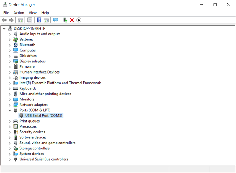
For example, this cable uses the Prolific hardware. The drivers are available on their site. If you are on Windows the driver can be installed after connecting C.H.I.P. Pro to your computer and navigating to Device Manager, finding Ports (COM & LPT) and double-clicking on the unrecognized USB-serial port. From the window that pops up, you will be able to tell the computer to go find the device’s driver online and install it.
Solder Headers to C.H.I.P. Pro
To connect the USB-UART cable to C.H.I.P. Pro you will need to solder headers onto the board for a reliable connection.

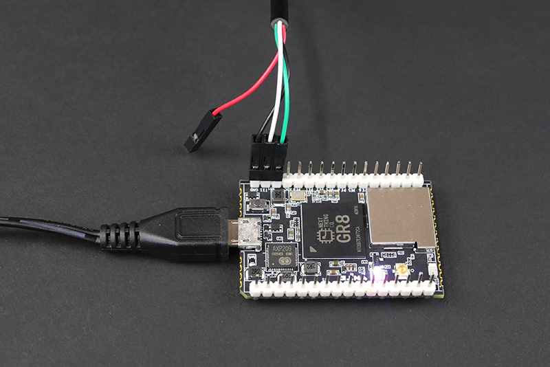
The below connections work for the cable linked to in the above material list. Make sure to check the manufacturer’s product description for the correct pinout for whichever cable you are using.
- black - GND
- green - RX
- white - TX
Power C.H.I.P. Pro
C.H.I.P. Pro can be powered through a computer’s USB port. However, some power intensive applications might require more current than the average computers provide via their USB port. A reliable way to power C.H.I.P. Pro is through the micro USB port using an AC/DC adapter (we recommend getting one that supplies 5V and 1 amp).
OS X & Linux
Mac systems and most flavors of Linux come with the terminal emulator software Screen. In case Screen is missing, it can be installed using apt-get on Debian-based systems:
sudo apt-get install screen
With C.H.I.P. Pro connected to your computer check to see if the usbserial port has appeared:
Mac
ls /dev/tty.*
The port name will be /dev/tty.usbserial or something similar.
Linux
ls /dev/ttyUSB*
The port name will be ttyUSB0 or something similar.
Connect
Use Screen to create a serial terminal connection at 115200 bps:
Mac
screen /dev/tty.usbserial 115200
Linux
screen /dev/ttyUSB0 115200
Once a terminal window pops up, hit the Enter key.
- For a Buildroot example you will automatically be logged in as
root. - For the Debian example, log in with the default username and password
chip.
Exit Screen
When done with Screen, press Ctrl+A then Ctrl+k to kill all windows and terminate Screen.
If you get the error “Cannot open line… Resource busy” when trying to connect via Screen it’s because the last session was not properly exited. Here is how kill an open session that was not disconnected:
Search for the open file and active process using usbserial:
lsof | grep usbserial
You will get an output that looks something like this:
screen 27127 Sefi 5u CHR 18,0 0t0 605 /dev/tty.usbserial
Note the process ID. In this case, it’s 27127. Then run:
screen -x 27127
This will return you to the previous screen session. Then use Ctrl+A Ctrl+K to close it (will ask you to confirm).
Windows
Download the PuTTY terminal emulator.
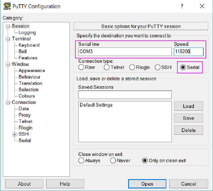
In Windows, open the Device Manager. Find and expand Ports (COM & LPT). Find the port labeled USB-to-Serial Port (COMx) and take note of the COMx port number. This is the port that the C.H.I.P. Pro is connected to.
In PuTTY choose Serial as the Connection type. Plug the following items in and click Open.
- COMx number as the Serial Line
- 115200 as the Speed (baud rate)
[ ] (images/ComPort.PNG) ] (images/ComPort.PNG) |
[ ] (images/puTTYsetM.jpg) ] (images/puTTYsetM.jpg) |
|---|---|
| In Device Manager find COM port # | Plug port # and baud rate into puTTY |
Once a terminal window pops up, press Enter.
- For a Buildroot example you will automatically be logged in as
root. - For the Debian example, log in with the default username and password
chip.
WiFi Antenna
-
Onboard WiFi and BT ceramic antenna: Unictron product no. H2U34WGTQW0100, model AA055.
-
External antenna included in the C.H.I.P. Pro Dev Kit: Wacosun model HCX-P321.
C.H.I.P. Pro comes with an onboard ceramic antenna that is intended for debugging purposes only. We recommend the use of an external antenna for all product applications. Use the antenna that comes with the C.H.I.P. Pro Dev Kit or obtain any of these officially supported ones:
| Antenna Model | Manufacturer | Gain | Antenna Type | Connection Type | Freq. Range (GHz) | Cable Length (mm) |
|---|---|---|---|---|---|---|
| AA107 | Unictron | 3.3 dBi | PCB | IPEX | 2.4 - 2.5 | 100 |
| HCX-P321 | Wacosun | 2 dBi | PCB | IPEX | 2.4 - 2.5 | 150 |
| FXP73.07.0100A | Taoglas | 2.5 dBi | PCB | IPEX | 2.4 - 2.483 | 100 |
| AA055 | Unictron | 2.5 dBi | Ceramic | SMT | 2.4 - 2.5 | n/a |
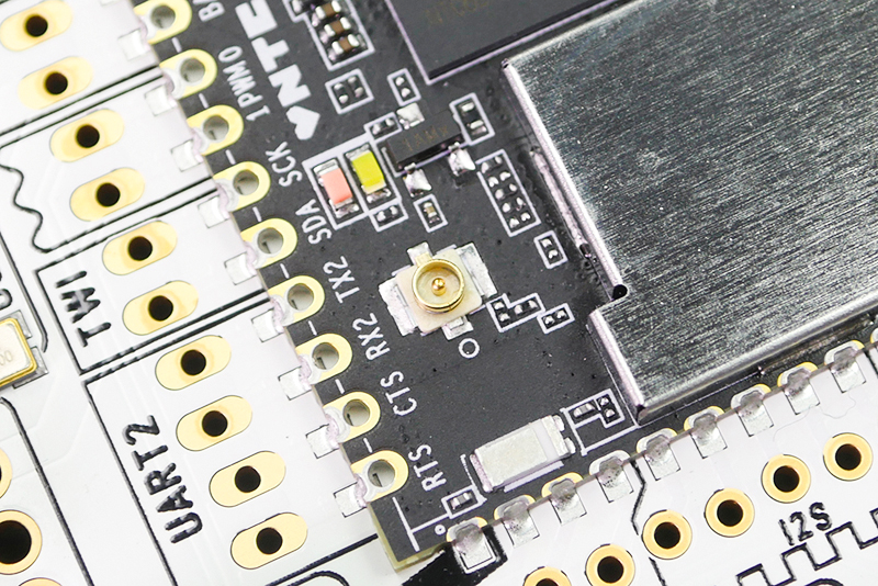
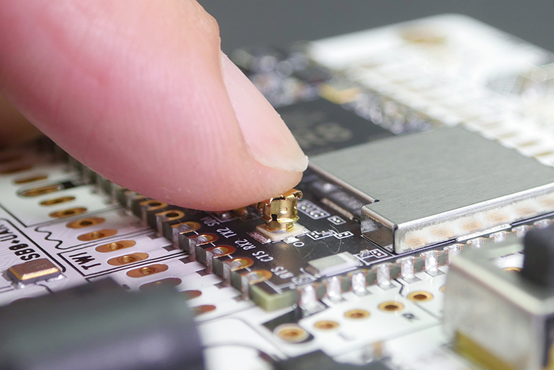
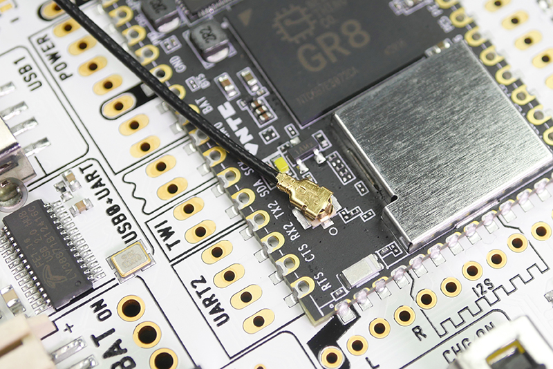
Connect Antenna
C.H.I.P. Pro uses a standard 50Ω IPEX (Hirose U.FL compatible) connector for the external antenna path.
To connect an antenna, come straight from the top and push the antenna onto the connector. Keep in mind the connector will wear out over time. We suggest keeping the disconnect/connect cycle down to 10 or less.
[ ] (images/wifiConnectB.jpg) ] (images/wifiConnectB.jpg) |
[ ] (images/wifiPush.jpg) ] (images/wifiPush.jpg) |
|---|---|
| WiFi antenna connector | Push antenna onto connector |
Enable Wifi Antenna
In order to use it, you need to set the path of the external antenna.
Buildroot
With the Buildroot C.H.I.P. Pro images comes a set_antenna script which accepts two arguments of either pcb or ufl depending on which you want to enable.
sh set_antenna pcb|ufl
Debian
In Debian, there are two ways to set the antenna path:
- The RF switch is connected to logic pin PB17, Sysfs GPIO #49. Manually set the logic states to choose either the onboard or external antenna.
0 = onboard-antenna
1 = external-antenna
wgetset_antenna script found here. Run and pass either thepcboruflargument, as stating above.
Edit Buildroot Examples
After connecting to the Dev Kit via USB-serial you can check out and edit the scripts for each Buildroot example. Use the Vi command-line editor to read and edit example scripts found in /usr/bin.
Blinkenlights
vi /usr/bin/blink-leds
vi /usr/bin/fade-pwms
VU-Meter
vi /usr/bin/vu-meter
Basic Vi Editor Commands
To edit text take Vi from command mode (default) to insert mode. Press the following keys to edit text.
- i - go into insert mode (to edit text)
- Esc - exit insert mode
Vi was built for Qwerty keyboards without arrow keys. They may work but if not, use these keys to move cursor:
- J - move down one line
- K - move up one line
- H - move left one character
- L - move right one character
Other helpful commands:
- u - undo last action
- :x then Enter - save and exit
- :q! then Enter - exit without saving
WiFi Setup: Buildroot
The Buildroot operating system uses the ConnMan command-line network manager to connect and manage your network connections.
Requirements
- C.H.I.P. Pro running Buildroot OS
- Serial connection to C.H.I.P. Pro
Step 1: Enable WiFi and Find a Network
These three commands will in turn, enable wifi, scan for access points, and list what networks are available:
connmanctl enable wifi
connmanctl scan wifi
connmanctl services
The services command has output similar to:
WaffleHouse          wifi_xxxxxxxxxxxx_xxxxxx_managed_psk
                	 wifi_xxxxxxxxxxxx_hidden_managed_psk
YOUR_NETWORK         wifi_xxxxxxxxxxxx_xxxxxx_managed_psk
    				 wifi_xxxxxxxxxxxx_xxxxxx_managed_none
Donut_Hut            wifi_xxxxxxxxxxxx_xxxxxxxxx_managed_psk
Step 2: Connect
Copy the string that starts with “wifi_’ to the right of the network name you want to connect to. If it has psk at the end, that means it is password protected (short for Wi-Fi Protected Access 2 - Pre-Shared Key) and you need to scroll further down to the " Password Protected” section.
No Password
To connect to YOUR_NETWORK, which has no password, services shows two choices. We want the one without psk in the string. Use the connect command:
connmanctl connect wifi_xxxxxxxxxxxx_xxxxxx_managed_none
If your network is not password protected, you’ll get some output that will indicate a successful connection, such as:
[  961.780000] RTL871X: rtw_set_802_11_connect(wlan0)  fw_state=0x00000008
[  962.070000] RTL871X: start auth
[  962.080000] RTL871X: auth success, start assoc
[  962.090000] RTL871X: rtw_cfg80211_indicate_connect(wlan0) BSS not found !!
[  962.100000] RTL871X: assoc success
[  962.110000] RTL871X: send eapol packet
[  962.290000] RTL871X: send eapol packet
[  962.300000] RTL871X: set pairwise key camid:4, addr:xx:xx:xx:xx:xx:xx, kid:0, type:AES
[  962.320000] RTL871X: set group key camid:5, addr:xx:xx:xx:xx:xx:xx, kid:1, type:AES
If your network is password protected you’ll get an error.
Password Protected
To deal with passwords you’ll need to put ConnMan into interactive mode:
connmanctl
This command gives a connmanctl prompt:
connmanctl>
In the shell, turn the agent on so it can process password requests:
agent on
Now use the connect command with your pasted wifi network string:
connect wifi_xxxxxxxxxxxx_xxxxxx_managed_psk
Enter your password when prompted:
  Agent RequestInput wifi_xxxxxxxxxxxx_xxxxxx_managed_psk
  Passphrase = [ Type=psk, Requirement=mandatory ]
  Passphrase?
You will be notified that you are connected:
Connected wifi_xxxxxxxxxxxx_xxxxxx_managed_psk
Exit connmanctl interactive mode:
quit
Step 3: Test Connection
Finally, you can test your connection to the internet with ping. Google’s DNS server at the IP address 8.8.8.8 is probably the most reliable computer on the internet, so:
ping -c 4 8.8.8.8
Expect ping to output some timing messages:
PING 8.8.8.8 (8.8.8.8): 56 data bytes
64 bytes from 8.8.8.8: seq=0 ttl=60 time=7.631 ms
64 bytes from 8.8.8.8: seq=1 ttl=60 time=7.474 ms
64 bytes from 8.8.8.8: seq=2 ttl=60 time=7.697 ms
64 bytes from 8.8.8.8: seq=3 ttl=60 time=9.004 ms

--- 8.8.8.8 ping statistics ---
4 packets transmitted, 4 packets received, 0% packet loss
round-trip min/avg/max = 7.474/7.951/9.004 ms
The -c 4 option means it will happen only 4 times.
✨ Congratulations! You are now Connected to a Network ✨
If your connection is not successful, then ping will tell you your network is down:
PING 8.8.8.8 (8.8.8.8): 56 data bytes
ping: sendto: Network is unreachable
Troubleshooting Connection Problems
-
Review any messages that the connect command gave you. Did they look like the examples of a successful connection?
-
Double check that you used the right network with the
connectcommand. -
If everything checked out until you got to
ping, there’s a good chance the problem is with your router or connection to the internet. Some networks have firewalls on them that will allow you to connect but prevent foreign devices from transferring information. -
Connman not Installed Error
If you try to use ConnMan and you get an error that it is not found or is not a command, chances are that you are using the Debian image. The ConnMan commands only apply to C.H.I.P. Pros running the Buildroot OS.
Disconnect from Network with Connman
To disconnect from your network, you might first want a reminder of the unfriendly string used to describe your access point:
connmanctl services
This command will output information about your current connection:
YOUR_NETWORK wifi_xxxxxxxxxxxx_xxxxxx_managed_psk
Copy and paste the string ID along with the disconnect command:
connmanctl disconnect wifi_xxxxxxxxxxxx_xxxxxx_managed_psk
You will be notified when it has disconnected:
Disconnected wifi_xxxxxxxxxxxx_xxxxxx_managed_psk
Forget Network with Connman
Generally, ConnMan will remember and cache setup information. This means that if you reboot in the vicinity of a known network, it will attempt to connect. However, if you need to forget a network setup, navigate to:
cd /var/lib/connman/
You can delete a single connection by seeing which are stored and copying the one you want to delete:
/var/lib/connman # ls
settings
wifi_xxxxxxxxxxxx_xxxxxx_managed_psk
wifi_xxxxxxxxxxxx_xxxxxx_managed_none
Then delete that connection:
rm -r wifi_xxxxxxxxxxxx_xxxxxx_managed_psk
You can delete all the “wifi” connections with:
rm -r wifi*
The -r is needed because these are directories you are deleting and the star at the end of wifi* assumes your connection IDs all start with the string “wifi”.
WiFi Setup: Debian
If you are using the Debian OS you will find that ConnMan is not installed, you will need to use Networking/CLI or the command nmcli instead.
Requirements
- C.H.I.P. Pro loaded with Debian
- Serial connection to C.H.I.P. Pro
Step 1: List available Wi-Fi networks
In terminal type:
nmcli device wifi list
The output will list available access points:
*  SSID      MODE   CHAN  RATE       SIGNAL  BARS  SECURITY
*  YOUR_NETWORK    Infra  11    54 Mbit/s  100     ▂▄▆█  --
   CatCafe         Infra  6     54 Mbit/s  30      ▂___  WPA1 WPA2
   2WIRE533        Infra  10    54 Mbit/s  44      ▂▄__  WPA1 WPA2
Step 2: Connect
You can connect to password protected or open access points.
No Password
To connect to an open network with no password:
sudo nmcli device wifi connect "YOUR_NETWORK_SSID" ifname wlan0
These commands will respond with information about the connection. A successful connection looks like:
Connection with UUID 'xxxxxxxx-yyyy-zzzz-xxxx-yyyyyyyyyyyy' created and activated on device 'wlan0'
Password Protected
To connect to a password protected network, use this command inserting your own network name and password:
sudo nmcli device wifi connect "YOUR_NETWORK_SSID" password "UR_NETWORK_PASSWORD" ifname wlan0
These commands will respond with information about the connection. A successful connection looks like:
Connection with UUID 'xxxxxxxx-yyyy-zzzz-xxxx-yyyyyyyyyyyy' created and activated on device 'wlan0'
Hidden SSID and Password Protected
To connect to a hidden and password-protected network:
sudo nmcli device wifi connect "YOUR_NETWORK_SSID" password "UR_NETWORK_PASSWORD" ifname wlan0 hidden yes
Step 3: Test your Connection
You can verify and test your wireless network connection.
Verify
nmcli device status
This outputs a list of the various network devices and their connections. For example, a successful connection would look like this:
DEVICE   TYPE      STATE         CONNECTION
wlan0    wifi      connected     YOUR_NETWORK
wlan1    wifi      disconnected  --
ip6tnl0  ip6tnl    unmanaged     --
lo       loopback  unmanaged     --
sit0     sit       unmanaged     --
Because it is worth knowing that Linux offers many ways of doing things, another command that shows your current active connection is:
nmcli connection show --active
Which outputs:
NAME  		   UUID                                  TYPE             DEVICE
YOUR_NETWORK   xxxxxxxx-yyyy-zzzz-xxxx-yyyyyyyyyyyy  802-11-wireless  wlan0
After you have connected once, C.H.I.P. Pro will automatically connect to this network next time you reboot (or start NetworkManager services).
Test
Expect ping to output some timing messages:
PING 8.8.8.8 (8.8.8.8): 56 data bytes
64 bytes from 8.8.8.8: seq=0 ttl=60 time=7.631 ms
64 bytes from 8.8.8.8: seq=1 ttl=60 time=7.474 ms
64 bytes from 8.8.8.8: seq=2 ttl=60 time=7.697 ms
64 bytes from 8.8.8.8: seq=3 ttl=60 time=9.004 ms

--- 8.8.8.8 ping statistics ---
4 packets transmitted, 4 packets received, 0% packet loss
round-trip min/avg/max = 7.474/7.951/9.004 ms
The -c 4 option means it will happen only 4 times.
✨ Congratulations! You are now Connected to a Network ✨
If your connection is not successful, then ping will tell you your network is down:
PING 8.8.8.8 (8.8.8.8): 56 data bytes
ping: sendto: Network is unreachable
Disconnect Network with Nmcli
Disconnect from the wireless device:
sudo nmcli dev disconnect wlan0
Forget Network with Nmcli
You may want to prevent auto-connection to a network. If so, you want the device to forget the a specific network. First, list the connections:
nmcli c
Which outputs something like:
NAME           UUID                                  TYPE             DEVICE
YOUR_NETWORK   xxxxxxxx-yyyy-zzzz-xxxx-yyyyyyyyyyyy  802-11-wireless  wlan0
Then, delete the network specified between quotes to forget it:
sudo nmcli connection delete id "YOUR_NETWORK"
Troubleshooting Connection Problems
- No Network Found
No network within range. If there’s no network, you can’t connect. Go find a network!
- Incorrect Password
If you type in the wrong password, you’ll get some errors like this:
[32258.690000] RTL871X: rtw_set_802_11_connect(wlan0) fw_state=0x00000008
[32258.800000] RTL871X: start auth
[32263.720000] RTL871X: rtw_set_802_11_connect(wlan0) fw_state=0x00000008
[32263.820000] RTL871X: start auth
[32264.430000] RTL871X: auth success, start assoc
[32269.850000] RTL871X: rtw_set_802_11_connect(wlan0) fw_state=0x00000008
[32269.970000] RTL871X: start auth
Error: Timeout 90 sec expired.
Try connecting again with the correct password.
- Failed Ping
If you don’t have access to the internet, your ping to an outside IP will fail.
It is possible that you can connect to a wireless network, but have no access to the internet, so you’d see a connection when you request device status, but have a failed ping. This indicates a problem or restriction with the router or the access point.
A failed ping looks something like:
From 192.133.2.10 icmp_seq=14 Destination Host Unreachable
From 192.133.2.10 icmp_seq=15 Destination Host Unreachable
From 192.133.2.10 icmp_seq=16 Destination Host Unreachable
18 packets transmitted, 0 received, +9 errors, 100% packet loss, time 17013ms
pipe 4
Change the router or access point permissions to allow a foreign board to connect to it. Alternatively, a personal mobile hotspot can obtained and used if you are in a work environment that can not change its network security settings.
- Loss of Wireless Network
A sudden, unplanned disconnection will post an error in the terminal window:
[30863.880000] RTL871X: linked_status_chk(wlan0) disconnect or roaming
The Network Manager will periodically try to reconnect. If the access point is restored, you’ll get something like this in your terminal window:
[31798.970000] RTL871X: rtw_set_802_11_connect(wlan0)
[31799.030000] RTL871X: start auth
[31799.040000] RTL871X: auth success, start assoc
[31799.050000] RTL871X: rtw_cfg80211_indicate_connect(wlan0) BSS not found !!
[31799.060000] RTL871X: assoc success
- Nmcli not Installed Error
If you try to use nmcli and you get an error that it is not found or is not a command, chances are that you are using a C.H.I.P. Pro Buildroot image. The nmcli commands only apply to C.H.I.P. Pro using Debian linux.
SSH
Once you connect to an network you can ssh into the C.H.I.P. Pro in order to program and control it. Our Debian example comes with ssh servers, our Buildroot examples do not. If you want to ssh while using Buildroot you will need to do a manual build.
Find IP
ip addr
The IP is on wlan0 or sometimes on wlan1.
Connect
ssh root@<CHIPproIP>
Access I/O via sysfs
C.H.I.P. Pro has a total of 27 GPIO pins ready for use:
- 2 PWM
- pins 9 & 10
- 3 input
- pins 39 - 41
- 22 input/output
- pins 11-16, 21-25, 30-38, 43 & 44
To see all the functions C.H.I.P. Pro pins offer check out the Multiplexing table.
GPIO is accessed through Linux’s sysfs interface.
Depending on the image that is flashed to C.H.I.P. Pro, the commands used to interact with the sysfs interface will differ. If using a Pro image, you need to act as root and use sudo sh -c with quotes around the command string. For example:
Pro (Debian)
sudo sh -c 'echo 132 > /sys/class/gpio/export'
Buildroot:
echo 132 > /sys/class/gpio/export
All PWM examples are done using one of NTC’s Buildroot based images.
GPIO Sysfs Numbers
To address a GPIO port via sysfs, you do not use the C.H.I.P. Pro or GR8 pin name. Sysfs sees the pins as another set of numbers. To find out what number to use for each GPIO pin reference the tables below.
Sysfs Pin Numbers
D0 - D7:
| C.H.I.P. Pro Pin # | 37 | 36 | 35 | 34 | 33 | 32 | 31 | 30 |
|---|---|---|---|---|---|---|---|---|
| sysfs # | 132 | 133 | 134 | 135 | 136 | 137 | 138 | 139 |
TWI1, UART2:
| C.H.I.P. Pro Pin # | 11 | 12 | 13 | 14 | 15 | 16 |
|---|---|---|---|---|---|---|
| sysfs # | 47 | 48 | 98 | 99 | 100 | 101 |
I2S:
| C.H.I.P. Pro Pin # | 21 | 22 | 23 | 24 | 25 |
|---|---|---|---|---|---|
| sysfs # | 37 | 38 | 39 | 40 | 41 |
SPI2:
| C.H.I.P. Pro Pin # | 41 | 40 | 39 | 38 |
|---|---|---|---|---|
| sysfs # | 128 | 129 | 130 | 131 |
PWM:
| C.H.I.P. Pro Pin # | 9 | 10 |
|---|---|---|
| sysfs # | 0 | 1 |
UART1:
** These pins are connected to the FE1.1S USB hub controller IC which is connected to the micro USB providing USB serial functionality. To use them as GPIO disable the USB hub controller by cutting the “UART Disconnect” traces.
| C.H.I.P. Pro Pin # | 44 | 43 |
|---|---|---|
| sysfs # | 195 | 196 |
Calculate sysfs Number
If a pin is not listed above you can calculate the sysfs number starting with the GR8 port number. All port numbers are printed on C.H.I.P. Pro for your convenience. They can also be found in the Allwinner R8 Datasheet starting on page 15.
As an example, take a look at D0 which is port PE4. Look at the letter that follows the “P”, in this case it’s “E”. Starting with A = 0, count up in the alphabet until you arrive at “E” and that is the letter index. For example, E=4.
Multiply the letter index by 32, then add the number that follows “PE”:
(4*32)+4 = 132
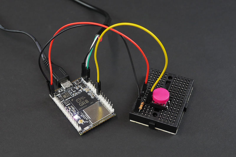
Digital Input Example
To access the GPIO pins through sysfs there is a process that must be adhered to. The following lines of code are an example that reads the changing state of pin PE4 which corresponds to 132 in sysfs.
When connecting a switch, we recommend adding a external pull-up or pull-down resistor to prevent a floating pin logic state.
In terminal, tell the system you want to listen to a pin by exporting it:
echo 132 > /sys/class/gpio/export
Next, the pin mode needs to be set. By default, the pin modes are set to input. So, the following command that views the mode will return “in” unless the pin mode was changed to “out” previously:
cat /sys/class/gpio/gpio132/direction
Connect a switch between pin PE4 and GND. Use this line of code to read the value:
cat /sys/class/gpio/gpio132/value
Continuously poll a switch on pin PE4(132) for its state change:
while ( true ); do cat /sys/class/gpio/gpio132/value; sleep 1; done;
Digital Output Example
Attach an LED to pin PE4 and ground. We recommend placing a current-limiting resistor in series to protect the GR8 module and LED from overcurrent or a potential short.
Change the mode of the pin from "in” to “out”:
echo out > /sys/class/gpio/gpio132/direction
Now that it’s in output mode, you can write a value to the pin and turn the LED on and off:
echo 1 > /sys/class/gpio/gpio132/value
echo 0 > /sys/class/gpio/gpio132/value
Blink an LED on Pin PE4(132)
while ( true ); do echo 1 > /sys/class/gpio/gpio132/value; cat /sys/class/gpio/gpio132/value; sleep 1; echo 0 > /sys/class/gpio/gpio132/value; cat /sys/class/gpio/gpio132/value; sleep 1; done;
Unexport GPIO
When you are done experimenting, always tell the system to stop listening to the gpio pin by unexporting it:
echo 132 > /sys/class/gpio/unexport
If pins are not unexported, the pins will be “busy” the next time you go to export them.
Power
Power C.H.I.P. Pro
C.H.I.P. Pro can be powered in a few ways that are all managed by the AXP209 power management IC.
Below is a list of the ports and pins to provide power to and pins that are necessary to initiate power in some instances.
- Micro USB port - Use a 5V AC/DC adapter (we recommend getting one that supplies 5V and 1 amp).
Pins
- CHG-IN - Connect 5 - 5.5 volts of power to this pin (and GND) to provide power for C.H.I.P. Pro. If you have a Lithium Polymer (LiPo) battery connected to BAT, then power provided to CHG-IN will also charge the battery.
- BAT - Connect a single-cell 3.7V LiPo battery to this pin (and GND) to provide power to C.H.I.P. Pro and receive charge from power inputs.
- PWR (PWRON) - Connect to ground for 1 second to turn C.H.I.P. Pro on when a battery is attached to the BAT pin.
- VBUS - Connect 5 volts to this pin (and GND to pin 53) to provide power to C.H.I.P. Pro. Power connected to VBUS will also charge a battery, just at a slower rate than from CHG-IN. The VBUS pin is the same one than in the microUSB connector.
Battery Charging and BTS Pin
C.H.I.P. Pro uses the AXP209 IC to manage battery charging. Pin 7 marked BATTEMP or BTS is directly connected to the TS pin on the AXP209. This pin supports a thermistor to monitor the battery temperature when the battery is charging or discharging. If you do not incorporate a thermistor into your setup the pin may float from ground interfering with how much charge current is throttled to the BAT pin and the JST connector. To ensure maximum charge current without a thermistor disable the battery temperature monitoring system.
There are two ways to do this:
- Connect BTS pin to ground
- Disable the temperature functionality in software:
sudo i2cset -y -f 0 0x34 0x82 0x82
The AXP209 IC is seen as a I2C device on C.H.I.P. Pro. By default the AXP209 is tuned for a 10KΩ 1% thermistor at 25°C with a programmable register for thermistor current to adapt to different devices. You can find more information on this setup in the AXP209 Datasheet. Search “ts pin” to quickly find information.
Power Out
C.H.I.P. Pro also has options for providing power to peripherals and sensors.
- VCC-3V3 - Provides 3.3V for sensors.
- IPSOUT - The Intelligent Power Select provides up to 2.5 amps at up to 5 volts, depending on power provided at CHG-IN or VBUS pins. If a 3.7V LiPo battery is the only source of power, IPSOUT will provide a bit less than 3.7 volts. In general, the voltage at IPSOUT is a bit less than voltage in, with a max voltage of 5 volts.
If you need to provide power to a USB device connected to USB1, connect IPSOUT to an appropriate switching regulator to the USB connector pad on your circuit board.
Powering Off
There are two ways to power off C.H.I.P. Pro:
1) Ideally, C.H.I.P. Pro should be powered off through a terminal window using the poweroff command. This will end all processes safely protecting your data.
2) On the board, connect PWR pin to GND for 3+ seconds to power off.
Technical Documents
C.H.I.P. Pro Datasheet
The complete datasheet for C.H.I.P. Pro is available in our C.H.I.P. Pro Hardware GitHub repo.
C.H.I.P. Pro Mechanical Drawing
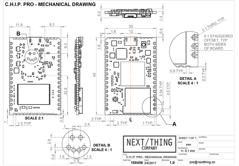
You can download a high resolution version of this image here.
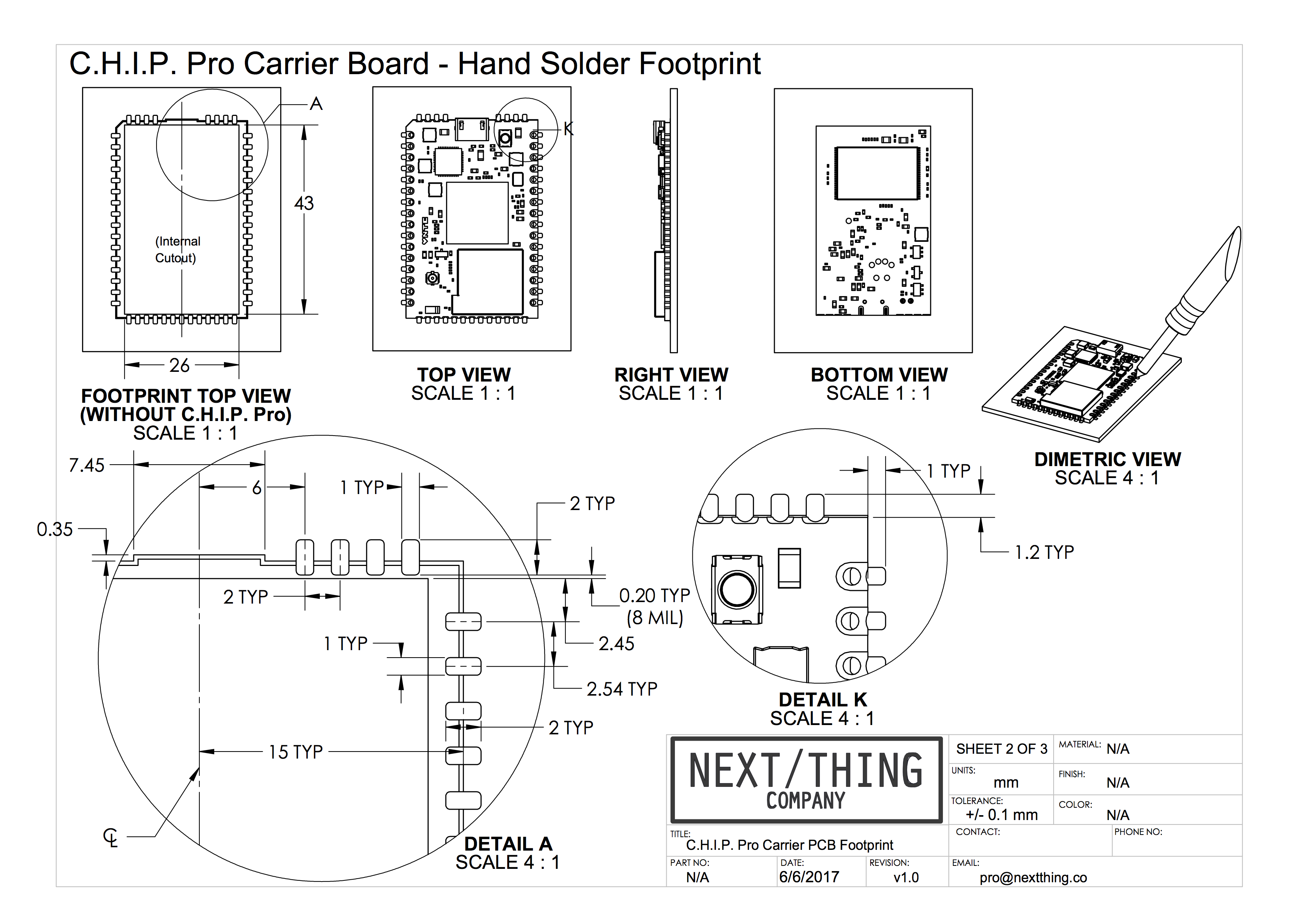
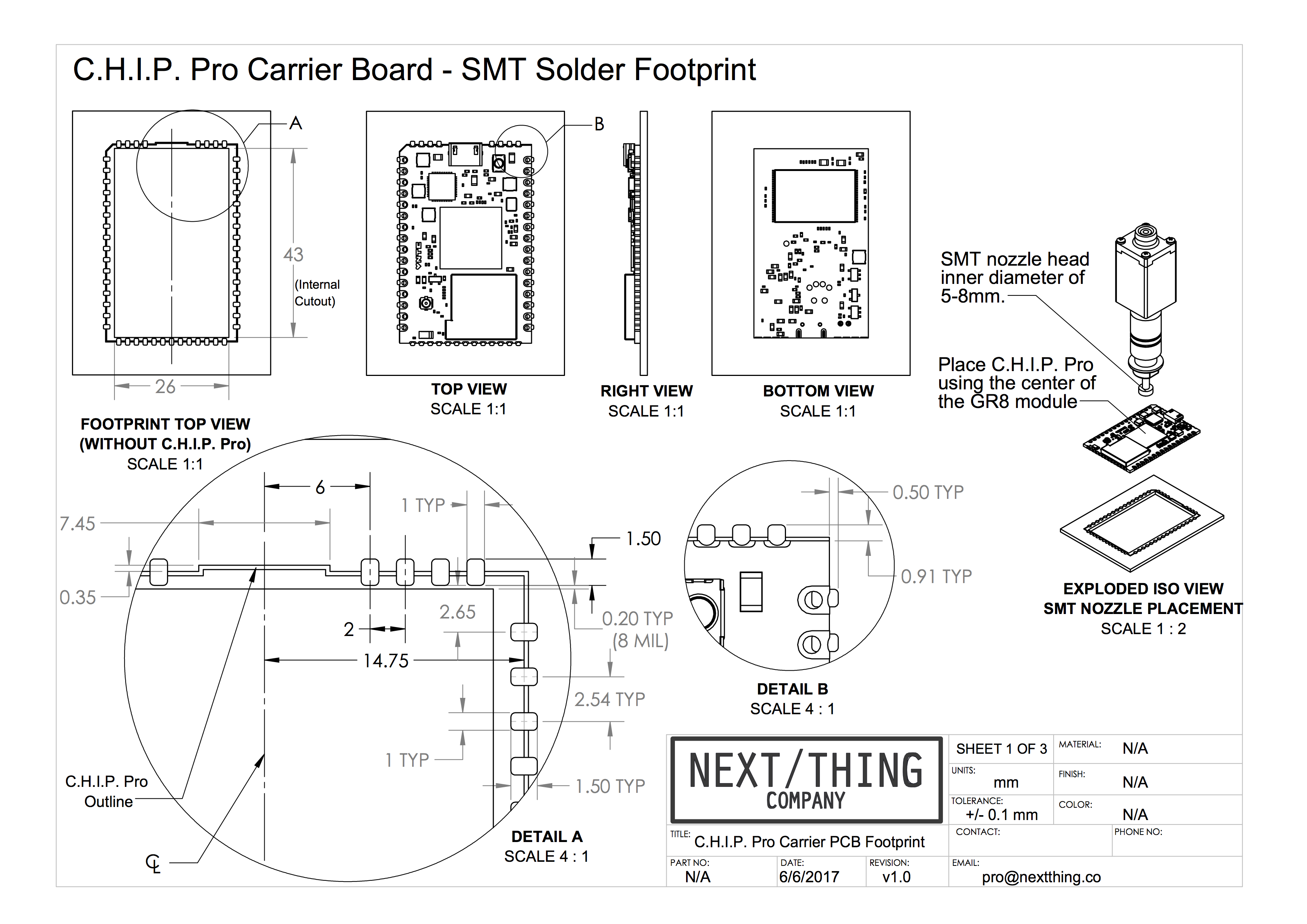
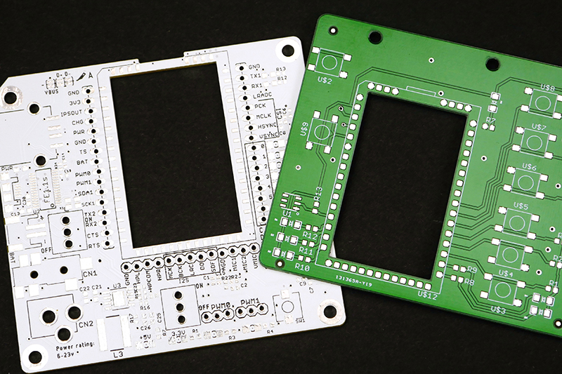
C.H.I.P. Pro PCB Footprint
C.H.I.P. Pro is designed for prototyping and dropping into a production assembly line. We have detailed diagrams for mounting C.H.I.P. Pro by hand soldering and by SMT pick-and-place machines to include in your PCB designs.
More detailed information on designing a PCB for C.H.I.P. Pro is found here.
GR8 Datasheet
Find the ballout diagram, technical specifications, and mechanical information in the GR8 datasheet available in our C.H.I.P. Pro Hardware Github repository in the GR8 directory. Looking for a reference design that uses GR8? Check out all the C.H.I.P. Pro design documents and schematics also available in the C.H.I.P. Pro Hardware repository.
GR8 Manual
All details needed to program GR8 are in the GR8 manual available in our Github repository.
Open Source License
C.H.I.P. Pro is open source hardware and software. Find all you need to build a C.H.I.P. Pro in our Github repo. Search our repositories for core and developing C.H.I.P. Pro software. For up-to-date announcements on software releases visit our website and sign up to our newsletter. Or, join the community on our forum where we actively post announcements.

This work is licensed under a Creative Commons Attribution 4.0 International License.
Specifications
C.H.I.P. Pro Exposed Interfaces
- 1x Two Wire Interface
- 2x UART (1x 2-wire and 1x 4-wire)
- SPI enabling SD card interface
- SPI Bus
- 2x PWM
- 6-bit ADC
- I2S Digital Audio
- S/PDIF IEC-60958 Digital Audio Input and Output
- 2x USB HS/FS/LS
- USB 2.0 Host
- USB 2.0 OTG
- Parallel Camera Interface
- 3.3V DC supply
- IPS dynamic power pass-through
- 27 GPIO
Audio
Stereo audio in and out is handled by an on-die 24-bit audio codec in GR8.
- 24-bit ADC/DAC for stereo audio in and out
- One-wire Audio (S/PDIF Compatible) digital out
- Supports 44.1 kHz, 48 kHz, 96 kHz, and 192 kHz sample rates
- Bi-directional I2S digital audio for interfacing with industry standard audio codecs
- Full-Duplex synchronous serial digital audio interfaces
- I2S Audio data sample rate from 8-192kHz
- Transmit and Receive FIFO buffers with programmable thresholds
Power and Battery Management
-
AXP209 power management IC connected to a dedicated I2C bus
-
Operating Voltage - 3.8V - 6.3V
-
Operating Temp - 40C - 130C
-
1.8A max battery charging current with programmable limits
-
2.5A max power distribution to system
C.H.I.P. Pro can be powered by battery, USB or AC/DC adapter. On-board Power management with the AXP209 provides plenty of power options to better match your applications: mobile, commercial, and low-power are all possible with C.H.I.P. Pro.
For more details, the AXP209 datasheet can be found here.
WiFi
- Realtek 8723DS Combination Module
- Bluetooth 4.2 LE
- 2.4GHz Wifi 802.11 b/g/n
- Wifi and BT Unictron antenna model no. AA055
- IPEX (U.FL) antenna connector
- FCC/CE/IC certified
A software controlled antenna path selects between the onboard chip antenna or a IPEX (U.FL) antenna connector where several pre-certified antennas can be added.
FCC Modular certification (47 CFR 15.212) limits the need for final device “intentional radiator” certification under 47 CFR 15.247, so long as pre-certified antennas are used with C.H.I.P. Pro.
To learn more, find the FN-Link Module antenna datasheet here
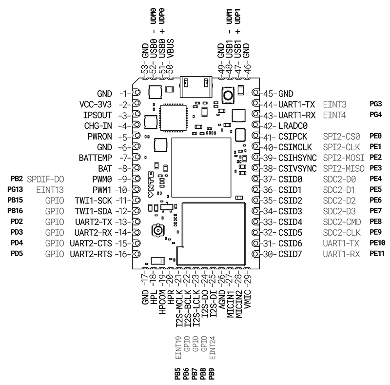
Pin Descriptions
Pinout Diagram
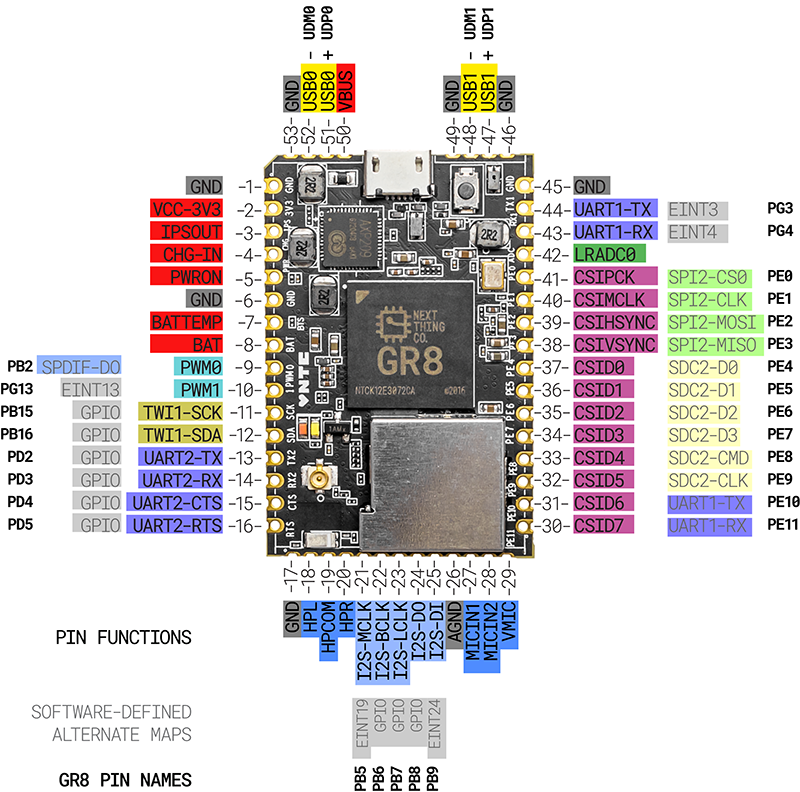
C.H.I.P. Pro has a number of specialized pins for input and output, plus 27 general purpose input and output (GPIO) pins. The image above shows the pin location and muxing on C.H.I.P. Pro, and the tables below organize pins according to their specialized functions.
- Pin Number
- Port
- GR8 Pin Name
- Signal Description
- Type
For more detailed information about pins on C.H.I.P. Pro and the GR8, please see the data sheets available here.
BATTEMP
| Pin Number | Port | AXP209 Pin Name | Signal Description | Type |
|---|---|---|---|---|
| 7 | NA | BATTEMP | Thermistor connection for battery heat detection | I |
PWM
| Pin Number | Port | GR8 Pin Name | Signal Description | Type |
|---|---|---|---|---|
| 9 | PB2 | PWM0 | Pulse Width Module Channel0 Output | O |
| 10 | PG13 | PWM1 | Pulse Width Module Channel1 Output | O |
TWI1
| Pin Number | Port | GR8 Pin Name | Signal Description | Type |
|---|---|---|---|---|
| 11 | PB15 | TWI1-SCK | TWI0 Clock | I/O |
| 12 | PB16 | TWI1-SDA | TWI0 Data/Address | I/O |
UART – Universal Asynchronous Receiver/Transmitter
| Pin Number | Port | GR8 Pin Name | Signal Description | Type |
|---|---|---|---|---|
| 44 | PG3 | UART1-TX | UART1 Data Transmit | O |
| 43 | PG4 | UART1-RX | UART1 Data Receive | I |
| 13 | PD2 | UART2-TX | UART2 Data Transmit | I |
| 14 | PD3 | UART2-RX | UART2 Data Receive | O |
| 15 | PD4 | UART2-CTS | UART2 Data Clear to Send | I |
| 16 | PD5 | UART2-RTS | UART2 Data Request to Send | I |
Audio Codec
| Pin Number | Port | GR8 Pin Name | Signal Description | Type |
|---|---|---|---|---|
| 26 | NA | AGND | Audio Codec Analog Ground | G |
| 19 | NA | HPCOM | Headphone Common Reference Output | AO |
| 18 | NA | HPL | Headphone Left Channel Output | AO |
| 20 | NA | HPR | Headphone Right Channel Output | AO |
| 27 | NA | MICIN1 | Microphone Input | AI |
| 28 | NA | MICIN2 | Microphone Input | AI |
| 29 | NA | VMIC | Bias Voltage Out | AO |
I2S
| Pin Number | Port | GR8 Pin Name | Signal Description | Type |
|---|---|---|---|---|
| 21 | PB5 | I2S-MCLK | I2S Master Clock | O |
| 22 | PB6 | I2S-BCLK | I2S Bit Clock | I/O |
| 23 | PB7 | I2S-LRCK | I2S Left/Right Channel Select Clock | I/O |
| 24 | PB8 | I2S-DO | I2S Data Output | O |
| 25 | PB9 | I2S-DI | I2S Data Input | I |
OWA – One Wire Audio
| Pin Number | Port | GR8 Pin Name | Signal Description | Type |
|---|---|---|---|---|
| 9 | PB2 | OWA-DO | OWA Data Output | O |
LRADC
| Pin Number | Port | GR8 Pin Name | Signal Description | Type |
|---|---|---|---|---|
| 42 | NA | LRADC0 | ADC Input Channel0 for Multi-Button Input | I |
SPI – Serial Peripheral Interface
| Pin Number | Port | GR8 Pin Name | Signal Description | Type |
|---|---|---|---|---|
| 41 | PE0 | SPI2-CS0 | SPI2 Chip Select Signal (active low) | I/O |
| 40 | PE1 | SPI2-CLK | SPI2 Clock Signal | I/O |
| 39 | PE2 | SPI2-MOSI | SPI2 Master Data Out, Slave Data In | I/O |
| 38 | PE3 | SPI2-MISO | SPI2 Master Data In, Slave Data Out | I/O |
D0-D7 – General Purpose In/Out
| Pin Number | Port Name | GR8 Pin Name | Signal Description | Type |
|---|---|---|---|---|
| 37-30 | D0-D7 | GPIO | Digital I/O | I/O |
CSI – Camera Sensor Interface
| Pin Number | Port Name | GR8 Pin Name | Signal Description | Type |
|---|---|---|---|---|
| 41 | PE0 | CSI-PCLK | CSI Pixel Clock | I |
| 40 | PE1 | CSI-MCLK | CSI Master Clock | O |
| 39 | PE2 | CSI-HSYNC | CSI Horizontal Sync | I |
| 38 | PE3 | CSI-VSYNC | CSI Vertical Sync | I |
| 37-30 | PE4-PE11 | CSI-Data[7:0] | CSI Data Bit | I |
SD/MMC
| Pin Number | Port Name | GR8 Pin Name | Signal Description | Type |
|---|---|---|---|---|
| 37-34 | PE4-PE7 | SDC2-D[3:0] | SDC2 Data Bit [3:0] | I/O |
| 33 | PE8 | SDC2-CMD | SDC2 Command Signal | I/O |
| 32 | PE9 | SDC2-CLK | SDC2 Clock | O |
External Interrupt
| Pin Number | Port Name | GR8 Pin Name | Signal Description | Type |
|---|---|---|---|---|
| 44 | PG3 | EINT3 | External Interrupt Input | I |
| 43 | PG4 | EINT4 | External Interrupt Input | I |
| 10 | PG13 | EINT13 | External Interrupt Input | I |
| 21 | PB5 | EINT19 | External Interrupt Input | I |
| 25 | PB9 | EINT24 | External Interrupt Input | I |
USB1 and USB0
| Pin Number | Port Name | GR8 Pin Name | Signal Description | Type |
|---|---|---|---|---|
| 52 | UDM0 | USB0-DM | USB0 D- Signal | A I/O |
| 51 | UDP0 | USB0-DP | USB0 D+ Signal | A I/O |
| 48 | UDM1 | USB1-DM | USB1 D- Signal | A I/O |
| 47 | UDP1 | USB1-DP | USB1 D+ Signal | A I/O |
| Pin Number | Port Name | AXP209 Pin Name | Signal Description | Type |
|---|---|---|---|---|
| 50 | VUSB | VBUS-USB | VBUS Power Supply | P |
Note: The on-board micro-USB connector is wired in parallel with the castellated edge points at VBUS, UDP0, UDM0, and GND. If you connect a USB host to both the castellated edges AND the connector, at best your USB will no longer work, at worst you may damage your equipment.
C.H.I.P. Pro FAQ
Ordering
How much does C.H.I.P. Pro cost?
C.H.I.P. Pro costs $16. To purchase, visit our web store or contact [email protected].
Are there quantity discounts?
C.H.I.P. Pro is $16 unless you are interested in purchasing 10K+ units. If that is the case please contact [email protected] to discuss a quantity discount.
Is C.H.I.P. Pro open source?
Yes! Find all you need to build with C.H.I.P. Pro in our Github repo.
This work is licensed under a Creative Commons Attribution 4.0 International License.
Where can I purchase C.H.I.P. Pro?
We offer the C.H.I.P. Pro Dev kit and C.H.I.P. Pro in our web store.
How many may I order?
As many or as few as you need: 1 to 1 million (or more). For orders over 1KU please contact [email protected] to set up a purchase order.
Building a Product with C.H.I.P. Pro
I made a C.H.I.P. prototype, will it be software and hardware compatible with C.H.I.P. Pro and the GR8 module?
GR8 has the same Allwinner R8 processor that is in C.H.I.P., so your C.H.I.P. software is 100% compatible with C.H.I.P. Pro. We believe you shouldn’t have to change your software to go into production.
To see some of the hardware differences between C.H.I.P. and C.H.I.P. Pro take a look at our comparison chart. Still have questions? Feel free to contact us at [email protected].
What certifications and directives is C.H.I.P. Pro in compliance with?
- CE
- IC
- FCC (Part 15 Modular Certification)
- Reach
- RoHS
Visit our Compliance Statement section for more information about each certification.
I have designed a circuit and am embedding C.H.I.P. Pro into a larger PCB design. Once it is integrated, do I need to get FCC and CE re-certification?
FCC
If you are designing a consumer product, you will need some certification but the time and money put into that process can be greatly reduced by leveraging our FCC Part 15 subpart C modular certification.
C.H.I.P. Pro is modularly certified for use with several external antennas in addition to the included on-board SMT ceramic antenna. A list of pre-cetified antennas are found in the C.H.I.P. Pro datasheet on page 11 and listed in the C.H.I.P. Pro online docs. Part 15 subpart C covers intentional radiation. If C.H.I.P. Pro is the only radio being used in your product’s final circuit and you use one of the precertified antennas you can meet requirements by completing a Declaration of Conformity (DoC) and affixing the FCC ID to your own product.
Most likely, your final product will still need to be tested for compliance under Part 15 subpart B for unintentional radiation.
For more information, we recommend you reach out to the Federal Communications Commision with any questions you have.
CE
THe CE Mark is a label placed on manufactured or imported goods in the European Union. C.H.I.P. Pro has been tested and is compliant with the Radio Equipment Directive (RED) which recognizes C.H.I.P. Pro as low power short range wireless device that can be sold within the European market.
If your product integrates C.H.I.P. Pro without modifying any of the radio frequency design and an addition of an antenna with greater gain than the certified ones, your product will likely still comply.
I am interested in creating a custom PCB that integrates C.H.I.P. Pro, where do I start?
To get started, refer to our PCB Design Guide. There, you will find recommendations of services to help aid you in PCB design and fabrication plus best practices. We are also happy to do a PCB review and help where we can. If you have questions reach out to us by emailing [email protected].
Do you offer custom flashing solutions?
We offer flashing of custom firmware at the factory for an extra fee when you purchase 1K+ C.H.I.P. Pros.
What companies have used C.H.I.P. Pro in their products?
There are several products in different R&D and production stages. Some that have been publicly announced and have made it to market are the following:
-
[Sandman Doppler Alarm Clock](https://www.paloaltoinnovation.com/collections/sandman-clo cks/products/sandmandoppler) by Palo Alto Innovation
-
TRNTBL by Vnyl
-
Voyager by Digital Sputnik
Power
Why is my battery charging at a very slow rate or not at all?
First, make sure the correct power source is connected to the correct pins as stated in the documentation.
Assuming the power source is connected correctly, the issue may be with C.H.I.P. Pro’s BTS pin which is directly connected to the TS pin on the AXP209 power management unit. This pin expects a 10K thermistor as a way to monitor the battery by providing the pin with a specific voltage range. Hitting this range tells the PMU that it is safe to charge the battery. Without an added thermistor, it’s recommended to disable this function by either connecting the BTS pin to ground or disabling through software. Read more about the BTS pin and how to disable it in the Power section of the C.H.I.P. Pro docs.
I think my C.H.I.P. Pro is overheating!
The cause of possible overheating issues is usually due to lack of a proper power source or a software issue. Check the most recent C.H.I.P. Pro datasheet for minimum and maximum power and temperature ratings.
There are a few reasons why your C.H.I.P. Pro may experience sudden power loss or a freeze, but heat is almost never the issue. Rest assured knowing that C.H.I.P. Pro has been tested and verified in various extreme temperatures.
My C.H.I.P. Pro shuts down during boot or when under heavy processing loads.
Make sure you are using an adequate power source that can provide a recommended 1 Amp of current. You can also attach a single cell LiPo battery to the BAT pin to provide extra power when the processor needs it.
Another common cause for sudden power loss is due to the AXP209’s power management shutting down if the current draw reaches a set threshold (900mA, for example). If your project has higher power needs, you may want to disable the current-limit feature and set it to “no limit” so that the AXP209 will allow the system to tolerate higher current. This can be found on page 33 of the AXP209 datasheet.
The common way to set this register is using a systemd service that issues the proper command with i2c-tools:
i2cset -f -y 0 0x34 0x30 0x03
If this register needs to be set earlier in the boot process, you can also accomplish this from U-boot:
i2c dev 0
i2c mw 0x34 0x30 0x03 2
My C.H.I.P. Pro is freezing when downloading or copying files.
If you are experiencing a freeze but C.H.I.P. Pro did not experience a power loss, this is most likely due to running out of storage space in the onboard memory. Try rebooting and freeing disk space in your file system.
If C.H.I.P. Pro loses power during these operations, it is most likely a problem with your power source.
How can I prevent data from being corrupted in the event of a power cut or some other kind of immediate shutdown?
The best practice is to try and ensure that your device never turns off without completing a proper shutdown procedure. For example, when adding a battery to your device, it is best to write code that will monitor battery usage and power down your system gracefully when the voltage drops below a specified threshold.
If this is not an option for your application, you can also try calling the sync command periodically when you are writing data. This ensures that the NAND blocks are synchronized and may eliminate data corruption in the case of a sudden power loss.
Is there an interrupt or some kind of event for the AXP209 power management?
A simple way to monitor power usage would be to write a script or service that queries the AXP209 on I2C bus 0 at periodic intervals.
The AXP209 has its own interrupts, which are connected to pin M2 (NMI) on the GR8. Currently, we do not provide documentation on how to use the NMI to respond to such events.
Hardware and Software
How do I set the default state of the I/O pins in GadgetOS?
Sometimes you may have a project where you need to set the state of the I/O as early as possible before Linux has fully booted. We can accomplish this by adding a script for the U-boot phase of the booting process.
In the gadget-buildroot folder, edit the following file for the board you’re using:
gadget-buildroot/gadget/board/nextthing/chippro/uboot-env
Let’s say we want to set the CSID6 (sysfs #138) and CSID7 (sysfs #139) pins to default to OUTPUT instead of INPUT. To do this, we need to add a function to the file like this:
set_gpio=gpio clear 138; gpio clear 139;
In this case, “clear” means resetting the I/O to an output state. You can also use commands like gpio toggle to invert the current value, gpio set to set the pin HIGH, or gpio input to set it as an input.
Now we need to call this function as early as possible in the boot process. In the same file, find this line:
preboot=run boot_fel
And change it to this:
preboot=run set_gpio; run boot_fel
Save this file and recompile your uboot changes.
/scripts/build-gadget make uboot-reconfigure all
Re-flash with the new build and reboot. Your I/O will now be set during the u-boot portion of the booting process.
NOTE: If you then export this pin when Linux is booted, it may revert back to its default state, so be sure to set it again.
Why is so much of my file system marked as “read only”?
With GadgetOS the intent was to make an operating system distribution that is as secure as possible when deployed to hundreds of devices all over the world. It was also important to limit the possibility of corrupted data during operations like over-the-air updates or sudden power loss.
Because of this, much of the root file system is set to “read only” to create as stable of a device as possible.
However, any files under the “/data” folder have full read/write access, so you should place any data that needs to be written in this location.
Why doesn’t my C.H.I.P. Pro (without the Dev Kit) register as a USB serial device when connected to my computer via the micro USB port?
If you are using GadgetOS, the micro USB port is configured as an ethernet gadget, which you can connect to using a shell application. If you want to use this as a USB serial port, you would need to make this change in the services running on the device and bind Getty to this port.
Alternatively, you can connect a USB UART cable to C.H.I.P. Pro’s UART1-RX and UART1-TX pins (pins 44 and 43) and communicate with it that way. This is essentially what the micro USB port does on the CHIP Pro Dev Kit.
I’m using Docker and I need to be able to reboot or shutdown my device from within a container. How can I do this?
The best practice would be write a script that runs outside of your Docker container which listens for some kind of event (a file change, a variable being set, etc). The script could then shut down once this event has been received from the Docker container. Another option is to install systemd on your device from the buildroot menu, although this will affect your boot time.
For a more brute force and lightweight approach, share the /proc directory with your container as a new volume. For example:
docker run -v /proc:/host/proc -it "test"
When your container is running, enter this command to synchronize the block devices and mount the read-only file system:
echo s > /host/proc/sysrq-trigger && echo u > /host/proc/sysrq-trigger && echo s > /host/proc/sysrq-trigger
Now to initiate a reboot, enter this command:
echo b > /host/proc/sysrq-trigger
Or to shutdown:
echo o > /host/proc/sysrq-trigger
What kind of flash memory does CHIP Pro or the GR8 support? (NAND, SD cards, eMMC, etc.)
Currently, C.H.I.P. and C.H.I.P. Pro officially support the following NAND components:
- 512mb Toshiba SLC NAND: TC58NVG2S0HTA00
- 4gb Toshiba MLC NAND: TC58TEG5DCLTA00
- 4gb Hynix MLC NAND: H27UCG8T2ETR
Can I add more flash memory by adding raw NAND Components?
Additional raw NAND components may work, but will most likely require changes to the Buildroot configuration. Additionally, there are two different branches of the Next Thing Co. Linux kernel depending on what type of NAND you have: SLC or MLC.
Can I boot From an SD Card?
Booting from SD cards or eMMC are supported on the GR8 processor, but since C.H.I.P. Pro already reserves these data pins for the onboard NAND storage, you would need to create a custom GR8 board with some additional Buildroot configuration settings.
How can I make a backup of my NAND or eMMC filesystem?
Using Rsync is the current recommended way to do this, as it will create a tar file of your root file system while excluding a few system directories. Here is an example of how you would use this command:
rsync -aAXv --exclude={"/dev/*","/proc/*","/sys/*","/tmp/*","/run/*","/mnt/*",”/etc/udev/rules.d/*”,"/media/*","/lost+found","/boot/*"} / /tmp/backup && tar -C /tmp/backup -cvzf myBackup.tar.gz .
How can I trigger an event when a USB device is added or removed?
Using udev rules is the recommended way of doing this, as you can specify a command to run when a device is added or removed. To learn more about udev functionality, please read Oracle’s documentation.
Can I connect an LCD or OLED display to C.H.I.P. Pro?
There is no HDMI, VGA, or composite video connections on C.H.I.P. Pro. However, any small resolution display with a controller board that supports an SPI or I2C interface should work. Additionally, it is also possible to reserve some of the available IO to drive an 8-bit parallel display with additional driver support and configuration.
If you wish to use the GR8 module to make your own board, it is possible to drive higher resolution displays up to 720p resolution by exposing the 8080 interface. There is also a composite video connection (sometimes known as CVBS or RCA) for use with older televisions or monitors. For more information, please consult the GR8 datasheet.
WiFi and Bluetooth
Why won’t GadgetOS use my settings from /etc/network/interfaces?
GadgetOS uses Connman to manage all network connections, which does not support /etc/network/interfaces and will override any of those settings. Instead, Connman uses its own settings file, which can be found here:
/var/lib/connman/*/settings
Our Debian C.H.I.P. Pro image called Pro uses nmcli for its network management, which does support /etc/network/interfaces. However, if using Gadget OS, this would have to be added to your kernel configuration with some additional settings.
Why am I getting poor WiFi signal strength and packet loss on my C.H.I.P. Pro?
C.H.l.P. Pro has the ability to use either the on-board ceramic SMT antenna or an external antenna via the onboard Hirose U.FL connector. Which antenna you should use depends on a few different factors (ground planes on the circuit board, location of power source in relation to the antenna connector, etc.)
For example, if you notice poor wifi performance when using the C.H.I.P. Pro Dev Kit, you may want to switch to use the external antenna, even if you don’t have anything physically connected to it.
To enable the external antenna, simply set pin PB17 (Sysfs GPIO pin #49) to HIGH. To enable the on-board SMT antenna, set it to LOW. This process can also be found in the C.H.I.P. Pro documentation page.
I built and flashed a custom version of GadgetOS, but my WiFi isn’t working.
It’s possible that you may need to tell GadgetOS to recompile the Realtek WiFi drivers. This can be done with the following command:
./scripts/build-gadget make linux-reconfigure uboot-reconfigure rtl8723ds_mp_driver-dirclean rtl8723ds_mp_driver-rebuild rtl8723ds_bt-dirclean rtl8723ds_bt-rebuild all
I’m using Bluez, but can’t find the hcid.conf file.
Bluez removed the ability to store PIN data in config files after version 3 due to security risks. At this time, Next Thing Co only provides official support for Bluez 5.
I install Bluez and tried to run “bluetoothctl”, but my system appears to have frozen.
Not to worry, your system did not freeze. (You can press Ctrl-C to exit bluetoothctl.) The most likely reason this is happening because you have not yet started the dbus service. You can do this manually by running “bluetoothd” first before running “bluetoothctl”.
What is the proper way to set Bluetooth’s MTU to reduce power consumption or change signal strength?
The recommended way is to add the Bluez 5.x package and then use tools such as “btgatt-client” and “btgatt-server”. Other utilities such as “hcitool” are deprecated and should no longer be used.
Bluetooth is not working on C.H.I.P. Pro Debian-based Pro image.
Currently, the Debian-based Pro image with built-in Bluetooth drivers is a work in progress. Since our software and hardware is open source for development, our community created an image that includes a working Bluetooth utility you can use to validate whether Bluetooth is working. Follow the instructions below to manually flash C.H.I.P. Pro with a Debian image that implements the Bluetooth stack using BlueZ.
These instructions are written for a development machine that runs a Debian distro of Linux. Depending on what OS your machine runs you will either need to install packages using a different package manager than apt-get or your dev machine may already include them.
- Install Git
sudo apt-get update
sudo apt-get install git -y
- Install necessary packages to update C.H.I.P. firmware
sudo apt-get install sunxi-tools u-boot-tools -y
git clone https://github.com/NextThingCo/CHIP-mtd-utils.git
cd CHIP-mtd-utils
make
sudo make install
- Clone CHIP-tools
git clone  https://github.com/NextThingCo/CHIP-tools.git
cd CHIP-tools
- Download tarball image from here
and place it in CHIP-tools directory. - Expand tarball
tar xf chip-ble.tar.gz
- Check to see that made a directory called
/img. - Set permissions to your username
sudo chown -R : img/
- Hold down the button on C.H.I.P. Pro and plug it into your development computer’s USB port to put CHIP Pro in FEL mode.
- While still holding down the button, run this command in terminal:
sudo ./chip-update-firmware.sh -L img/
- After you see
fastboot...OKyou can release the button and wait for the flashing to finish. Once it does, you will get a message that"CHIP is ready to roll!". - Unplug CHIP Pro and plug back in. Connect via UART-serial and login.
- Start the interactive
bluetoothctlcommand.
sudo bluetoothctl
- scan, pair and connect to devices
scan on
pair [MAC ADDRESS]
connect [MAC ADDRESS]
scan off
Original forum post.
GR8 FAQ
How much does GR8 cost?
Gr8 costs $6 in any quantity.
Where can I purchase GR8?
Contact us at [email protected] to tell us more about your product and to set up a purchase order.
What are GR8’s dimensions?
14mm x 14mm x 0.8mm
What is the GR8 package?
GR8 is built within a 252 ball FBGA (Fine Pitch Ball Grid Array) package, 0.8mm pitch.
I have a prototype of my product, should I choose C.H.I.P. Pro or GR8 to move forward with?
This depends on your product’s needs and your company’s resources. For most customers, C.H.I.P. Pro will be the best and most convenient way to work with the GR8 SiP. C.H.I.P. Pro contains 127 already sourced components including a power management unit (PMU), micro USB port, WiFi, Bluetooth and more.
If you have tried C.H.I.P. Pro and have found that you need a different layout and different functionality, then designing a custom PCB around GR8 is a great option. You can find out everything that GR8 has to offer in the GR8 datasheet.
I’m sourcing components for a custom PCB, which components work with GR8 out of the box?
The best reference for components that are supported by our operating systems out of the box is C.H.I.P. Pro. To see if they are right for your product, datasheets for these components are found in our C.H.I.P. Pro Hardware Github repo.
What WiFi Modules Does GR8 support?
Technically, a WiFi module supported in Arch Linux ARM and that uses the SDIO (Secure Digital Input Output) V2.0 protocol can be used with GR8. A good reference for components supported by our software is C.H.I.P. Pro which uses the RTL8723DS module.
What module you want to use may also depend on what kind of software support is available. Software drivers for the RTL8723DS module come with our C.H.I.P. Pro operating system making it a go-to choice if you need something that works right away.
For more information on the SDIO protocol, please refer to the specifications found on page 221 of the GR8 manual.
I’m a distributor, can I carry GR8?
Yes! Contact us at [email protected].
GR8 Pins and Multiplexing on C.H.I.P. Pro
Key
italics = default pin function
In the “On C.H.I.P. Pro” column:
- C.H.I.P. Pro pin number = exposed external pins on C.H.I.P. Pro
- NAND = available internal pins on C.H.I.P. Pro
- “n/e” = not exposed for use on C.H.I.P. Pro
| Function | Pin Name | On C.H.I.P. Pro | Multi2 | Multi3 | Multi4 | Multi5 | Multi6 | Multi7 | |
|---|---|---|---|---|---|---|---|---|---|
| PB(21) | PB0 | n/e | TWI0_SCK | ||||||
| PB1 | n/e | TWI0_SDA | |||||||
| PB2 | 9 | PWM0 | SPDIF_DO | EINT16 | |||||
| PB3 | n/e | IR_TX | EINT17 | ||||||
| PB4 | n/e | IR_RX | EINT18 | ||||||
| PB5 | 21 | I2S_MCLK | EINT19 | ||||||
| PB6 | 22 | I2S_BCLK | EINT20 | ||||||
| PB7 | 23 | I2S_LRCK | EINT21 | ||||||
| PB8 | 24 | I2S_DO | EINT22 | ||||||
| PB9 | 25 | I2S_DI | SPDIF_DI | EINT23 | |||||
| PB10 | n/e | SPI2_CS1 | SPDIF_DO | EINT24 | |||||
| PB11 | n/e | SPI2_CS0 | JTAG_MS0 | EINT25 | |||||
| PB12 | n/e | SPI2_CLK | JTAG_CK0 | EINT26 | |||||
| PB13 | n/e | SPI2_MOSI | JTAG_DO0 | EINT27 | |||||
| PB14 | n/e | SPI2_MISO | JTAG_DI0 | EINT28 | |||||
| PB15 | 11 | TWI1_SCK | |||||||
| PB16 | 12 | TWI1_SDA | |||||||
| PB17 | n/e | TWI2_SCK | |||||||
| PB18 | n/e | TWI2_SDA | |||||||
| PC(20) | PC0 | NAND | NWE | SPI0_MOSI | |||||
| PC1 | NAND | NALE | SPI0_MISO | ||||||
| PC2 | NAND | NCLE | SPI0_CLK | ||||||
| PC3 | NAND | NCE1 | SPI0_CS0 | ||||||
| PC4 | NAND | NCE0 | |||||||
| PC5 | NAND | NRE | |||||||
| PC6 | NAND | NRB0 | SDC2_CMD | ||||||
| PC7 | NAND | NRB1 | SDC2_CLK | ||||||
| PC8 | NAND | NDQ0 | SDC2_D0 | ||||||
| PC9 | NAND | NDQ1 | SDC2_D1 | ||||||
| PC10 | NAND | NDQ2 | SDC2_D2 | ||||||
| PC11 | NAND | NDQ3 | SDC2_D3 | ||||||
| PC12 | NAND | NDQ4 | SDC2_D4 | ||||||
| PC13 | NAND | NDQ5 | SDC2_D5 | ||||||
| PC14 | NAND | NDQ6 | SDC2_D6 | ||||||
| PC15 | NAND | NDQ7 | SDC2_D7 | ||||||
| PC19 | NAND | NDQS | UART2_RX | UART3_RTS | |||||
| PD2 | 13 | LCD_D2 | UART2_TX | ||||||
| PD3 | 14 | LCD_D3 | UART2_RX | ||||||
| PD4 | 15 | LCD_D4 | UART2_CTS | ||||||
| PD5 | 16 | LCD_D5 | UART2_RTS | ||||||
| PD6 | n/e | LCD_D6 | ECRS | ||||||
| PD7 | n/e | LCD_D7 | ECOL | ||||||
| PD10 | n/e | LCD_D10 | ERXD0 | ||||||
| PD11 | n/e | LCD_D11 | ERXD1 | ||||||
| PD12 | n/e | LCD_D12 | ERXD2 | ||||||
| PD13 | n/e | LCD_D13 | ERXD3 | ||||||
| PD14 | n/e | LCD_D14 | ERXCK | ||||||
| PD15 | n/e | LCD_D15 | ERXERR | ||||||
| PD18 | n/e | LCD_D18 | ERXDV | ||||||
| PD19 | n/e | LCD_D19 | ETXD0 | ||||||
| PD20 | n/e | LCD_D20 | ETXD1 | ||||||
| PD21 | n/e | LCD_D21 | ETXD2 | ||||||
| PD22 | n/e | LCD_D22 | ETXD3 | ||||||
| PD23 | n/e | LCD_D23 | ETXEN | ||||||
| PD24 | n/e | LCD_CLK | ETXCK | ||||||
| PD25 | n/e | LCD_DE | ETXERR | ||||||
| PD26 | n/e | LCD_HSYNC | EMDC | ||||||
| PD27 | n/e | LCD_VSYNC | EMDIO | ||||||
| PE(12) | PE0 | 41 | TS_CLK | CSI_PCLK | SPI2_CS0 | EINT14 | |||
| PE1 | 40 | TS_ERR | CSI_MCLK | SPI2_CLK | EINT15 | ||||
| PE2 | 39 | TS_SYNC | CSI_HSYNC | SPI2_MOSI | |||||
| PE3 | 38 | TS_DVLD | CSI_VSYNC | SPI2_MISO | |||||
| PE4 | 37 | TS_D0 | CSI_D0 | SDC2 D0 | |||||
| PE5 | 36 | TS_D1 | CSI_D1 | SDC2 D1 | |||||
| PE6 | 35 | TS_D2 | CSI_D2 | SDC2 D2 | |||||
| PE7 | 34 | TS_D3 | CSI_D3 | SDC2 D3 | |||||
| PE8 | 33 | TS_D4 | CSI_D4 | SDC2 CMD | |||||
| PE9 | 32 | TS_D5 | CSI_D5 | SDC2 CLK | |||||
| PE10 | 31 | TS_D6 | CSI_D6 | UART1 TX | |||||
| PE11 | 30 | TS_D7 | CSI_D7 | UART1 RX | |||||
| PF(6) | PF0 | n/e | SDC0_D1 | JTAG_MS1 | |||||
| PF1 | n/e | SDC0_D0 | JTAG_DI1 | ||||||
| PF2 | n/e | SDC0_CLK | UART0_TX | ||||||
| PF3 | n/e | SDC0_CMD | JTAG_DO1 | ||||||
| PF4 | n/e | SDC0_D3 | UART0_RX | ||||||
| PF5 | n/e | SDC0_D2 | JTAG_CK1 | ||||||
| PG(14) | PG0 | n/e | GPS_CLK | EINT0 | |||||
| PG1 | n/e | GPS_SIGN | EINT1 | ||||||
| PG2 | n/e | GPS_MAG | EINT2 | USB0-IDDET | |||||
| PG3 | n/e | SDC1_CMD | MS_BS | UART1_TX | EINT3 | ||||
| PG4 | n/e | SDC1_CLK | MS_CLK | UART1_RX | EINT4 | ||||
| PG5 | n/e | SDC1_D0 | MS_D0 | UART1_CTS | EINT5 | ||||
| PG6 | n/e | SDC1_D1 | MS_D1 | UART1_RTS | UART2_RTS | EINT6 | |||
| PG7 | n/e | SDC1_D2 | MS_D2 | UART2_TX | EINT7 | ||||
| PG8 | n/e | SDC1_D3 | MS_D3 | UART2_RX | EINT8 | ||||
| PG9 | n/e | SPI1_CS0 | UART3_TX | EINT9 | |||||
| PG10 | n/e | SPI1_CLK | UART3_RX | EINT10 | |||||
| PG11 | n/e | SPI1_MOSI | UART3_CTS | EINT11 | |||||
| PG12 | n/e | SPI1_MISO | UART3_RTS | EINT12 | |||||
| PG13 | 10 | SPI1_CS1 | PWM1 | UART2_CTS | EINT13 | ||||
| TVOUT | TVOUT | n/e | |||||||
| USB | UDM0 | 52 | |||||||
| UDP0 | 51 | ||||||||
| UDM1 | 48 | ||||||||
| UDP1 | 47 | ||||||||
| VCC_USB | n/e | ||||||||
| TP | TPX1 | n/e | |||||||
| TPX2 | n/e | ||||||||
| TPY1 | n/e | ||||||||
| TPY2 | n/e | ||||||||
| LINEINL | n/e | ||||||||
| LINEINR | n/e | ||||||||
| MIC1OUTP | n/e | ||||||||
| MIC1OUTN | n/e | ||||||||
| VMIC | n/e | ||||||||
| MICIN2 | 28 | ||||||||
| MICIN1 | 27 | ||||||||
| VRA1 | n/e | ||||||||
| VRA2 | n/e | ||||||||
| AVCC | n/e | ||||||||
| VRP | n/e | ||||||||
| AGND | n/e | ||||||||
| HPR | 20 | ||||||||
| HPCOM | 19 | ||||||||
| HPCOMFB | n/e | ||||||||
| VCC_HP | n/e | ||||||||
| HPBP | n/e | ||||||||
| HPL | 18 | ||||||||
| LRADC | LRADC0 | 42 | |||||||
| LRADC1 | n/e |
Compliance Statement
C.H.I.P. Pro is officially certified for CE, IC and FCC for use with multiple commercially available external antennas as well as the onboard ceramic SMT antenna. Find all Test Reports and Certificates in the C.H.I.P. Pro Hardware repository.
FCC
FCC ID: 2AF9F-1337R
C.H.I.P. Pro complies with part 15 subpart C of the FCC Rules. Operation is subject to the following two conditions:
- This device may not cause harmful interference.
- This device must accept any interference received, including interference that may cause undesired operation.
C.H.I.P. Pro has FCC Modular Transmitter certification meaning any product with C.H.I.P. Pro as the only active radio transmitter will not require your company to run certification testing for the Intentional Radiator portion of FCC tests. When you list that your product contains our FCC-ID’d module you avoid the need to apply for a new FCC-ID.
This greatly lessens the workload of taking your product through FCC certification. Your product will probably still need to be tested and state compliance with FCC Part 15 subpart B for Unintentional Radiation limits.
CE + RED 2014/53/EU
The CE mark on CHIP Pro enables the free movement of products into and within the European market. C.H.I.P. Pro is in compliance with the European Union’s Radio Equipment Directive for wireless transmitters and receivers.
Industry Canada
IC: 20863-1337R
This device complies with Industry Canada license-exempt RSS standard(s). Operation is subject to the following two conditions:
- This device may not cause harmful interference;
- This device must accept any interference received, including interference that may cause undesired operation of the device.
Cet appareil est conforme à Industrie Canada une licence standard RSS exonérés (s). Son fonctionnement est soumis aux deux conditions suivantes:
- Cet appareil ne doit pas provoquer d’interférences
- Cet appareil doit accepter toute interférence reçue, y compris les interférences pouvant provoquer un fonctionnement indésirable de l’appareil.
Information to User
CAUTION: Changes or modifications not expressly approved for compliance could void your authority to operate this equipment.
For any questions, reach out to us at [email protected].
PCB Design Guide
C.H.I.P. Pro was created to be seamlessly embedded into products and we at NTC are here to help you do that. If you are ready to go from breadboard to PCB, read on. This section gives recommendations and provides resources and tips to help plan a successful PCB design.
From 1 to 1MM
To make scaling up efficient and easy, C.H.I.P. Pro is offered in small and large quantities. Purchase from the online store or, for larger orders, email [email protected].
Tech Documents
NTC hardware and software is open source for development. You will find the following design and technical documents for C.H.I.P. Pro and C.H.I.P. Pro Dev Kit on our Github account.
- C.H.I.P. Pro datasheet
- Component datasheets
- Mechanical documents
- C.H.I.P. Pro schematics
- C.H.I.P. Pro Dev Kit schematics
- PCB board files
- Eagle Footprint
C.H.I.P. Pro Footprint
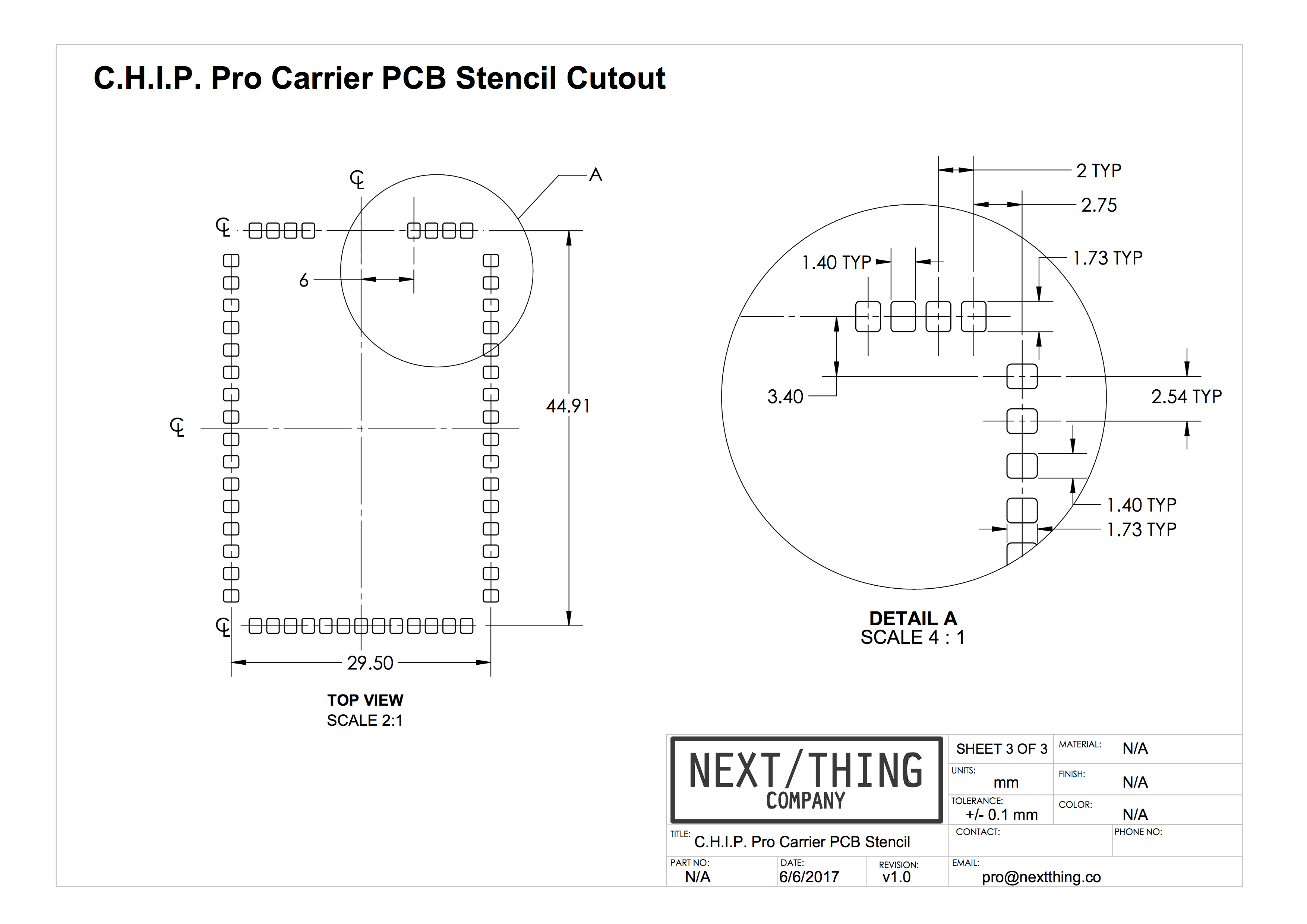
Create a C.H.I.P. Pro footprint with the EDA (Electronic Design Automation) software of your choice using the measurements provided in our footprint diagrams. For SMT manufacturing, you will also find a solder paste stencil.
SMT Footprint
Solder Paste Stencil
Hand Solder Footprint
If using Eagle software to design your PCB with, we’ve taken away the need to design one. Find our ready-made Eagle footprint here.
Do you want to share a footprint that you have created with us? We would like to include it here for others to use. Send your footprint to [email protected].
PCB Software and Services
There are many software packages and services to design and manufacture a PCB with. If you are just starting out in PCB design or want to explore other options we offer suggestions below.
The tools and services chosen are based on what we have seen used in the field and community across all levels of development. NTC does not officially recommend one EDA software package. The effectiveness of a design tool will depend on the user’s preferences and skill level.
EDA Software
-
OrCAD is a collection of tools used to design PCBs, schematics, analyze circuits with and more. Learn how to use their schematic design tool Capture through interactive tutorials.
-
A free and open source software suite. Design schematics, layout PCBs, and verify design for manufacturing. There are plenty of tutorials to learn from on their website.
-
A cloud-based software suite that has free and professional priced packages. Not only can you design PCBS, they offer circuit simulation and take PCB fabrication orders through their website. Footprints to components can be designed and contributed by community members for use by anyone. A user contributed footprint for C.H.I.P. Pro can be found by searching CHIP_Pro in libraries. Get started with EasyEDA’s online tutorials.
-
Eagle is powerful PCB design and schematic layout software. It’s well used and has a strong community behind it. There are plenty of tutorials found online, such as at Sparkfun, Adafruit, and YouTube. Start by reading an overview of the software and finding links to tutorials, example projects and more on Eagle’s product page. Find our C.H.I.P. Pro Eagle compatible footprint for download above.
-
Used by professionals and advanced hobbyists. A bigger learning curve comes with Altium but it is worth the time invested if you plan on continuing to design production ready PCBs.
PCB Fabrication Services
When you are ready to get your board fabricated you will need to choose a PCB manufacturer. Your choice will be based on a number of factors including, turn around time, board features (flex and color options) and scale of order. All of the services listed do small quantities to get you started. Some do large scale and offer multi-layer boards and other advanced services.
-
Several pricing options to choose from depending on what your board design specifications are. Many board features available with no minimum quantity. Design and assembly services are also offered.
-
No minimums, fast turn around and easy to use interface for uploading board designs and getting a quote. They offer flexible pcbs, SMD (surface mount device) stencils and assembly services.
-
AllPCB offers low prices and quality services in small and large scale batches. Their website is comprehensive with instant quote services and a way to upload your BOM and search for specific components.
-
Seeed Fusion PCB & PCB Assembly
They offer layout, manufacturing and assembly services along with other CNC services such as 3D printing and milling. They even offer several PCB colors options with their cheapest fabrication option.
-
OSH Park does batch manufacturing meaning that your board gets created with others on the same panel. This affects the turn around time making them the slowest option on the list. However, their straight forward and simple ordering interface makes it very easy to upload and check a board design in minutes.
Verify Manufacturer Design Rules
PCB manufacturers have specifications outlining their production capabilities called “design rules”. These design rules include smallest possible traces, drill hole size, spacing, etc. Most PCB design software have an automated process that checks your design against these design rules using files. This is called the DRC (design rule checking) process. If the design software you are using does not have this feature some board manufacturers offer the service or you can use DRC specific software.
As an example, OSH Park’s PCB design rules are found on their OSH Park Design Submission Guidelines page. Conveniently, they provide a file for checking PCB designs using Eagle software. OSH Park also provides design guideline documents for many of the EDA software people submit designs with. To get you started, below are some design rule resources for software linked to in this doc.
Power Considerations
Supplying Power to C.H.I.P. Pro
Powering C.H.I.P. Pro via the CHG-IN pin at 5-5.5V is the suggested route for all embedded applications. A reliable 2A+ rated power supply works well to power C.H.I.P. Pro.
C.H.I.P. Pro can also be battery powered through BAT, and by a USB charger/supply connected to VBUS.
Recommended Operating Voltage
| Pin | Min | Typical | Max | Unit |
|---|---|---|---|---|
| CHG-IN | 3.8 | 5-5.5 | 6.3 | V |
| BAT | 3.0 | 3.8 | 4.2+/-0.5% | V |
| VBUS | 3.8 | 5-5.5 | 6.3 | V |
PMU (Power Management Unit) Vout Current Available Before Loading Battery
| Iout | Min | Typical | Max |
|---|---|---|---|
| PMU Vout | 500 mA | 900 mA | 2500 mA |
A programmable current limit can be set in software allowing for safe attachment to USB 2.0, USB 3.0, or high-current CHG-In sources. Check the AXP209 datasheet.
for more information starting on page 33. The current set options are 100mA, 500mA, 900mA and “no limit”. C.H.I.P. Pro is set to 900mA upon boot by default.
Keep in mind that if the current draw spikes and exceeds the threshold even momentarily this will cause a brownout and C.H.I.P. Pro will shut down.
Power Consumption
Like any feature-loaded SOM, how much current C.H.I.P. Pro draws depends on what you need it to do. The following measurements are offered as a rough starting point with which to begin to understand the range of power budgets relevant to a CHIP Pro-based device operated from a battery. Exact power consumption is significantly influenced by factors such as software power optimizations (or lack thereof), power source quality, external peripheral circuitry, and ambient operating conditions.
| System State | Measurement | Value |
|---|---|---|
| Idle at Linux Shell | Supply (BAT) | 4.17V |
| Current | 125.90 mA | |
| Power | 525.00 mW | |
| Playing Local Audio | Supply (BAT) | 4.17V |
| Current | 209.40 mA | |
| Power | 873.62 mW | |
| WiFi Pinging | Supply (BAT) | 4.17V |
| Current | 184.70 mA | |
| Power | 770.20 mW | |
| Standby | Supply (BAT) | 4.17V |
| Current | 5.30 mA | |
| Power | 22.10 mW | |
| Shutdown | Supply (BAT) | 4.17V |
| Current | 1.60 mA | |
| Power | 6.67 mW |
Battery and BTS Pin
Thinking of including a rechargeable battery as a product feature? Read on to learn more about the BTS pin.
Pin 7 on C.H.I.P. Pro is marked BATTEMP or BTS and is directly connected to the TS pin on the AXP209 PMU. This pin supports a 10KΩ 1% thermistor to monitor the battery temperature when the battery is charging or discharging. If you do not incorporate a thermistor into your circuit the pin may float from ground interfering with how much charge current is throttled to the BAT pin and the JST connector.
To ensure maximum charge current without a thermistor disable the battery temperature monitoring system by one of two ways:
- Connect BTS pin to ground
- Disable the temperature functionality in software:
sudo i2cset -y -f 0 0x34 0x82 0x82
You can find more information on this setup in the AXP209 Datasheet starting on page 21.
Power Button
The PWRON pin can be connected to GND through a button as a Power Enable Key (PEK) or hibernation/wake button. The AXP209 can automatically identify long and short button presses. Read more about this on page 10 of the AXMP209 datasheet.
Additional USB Port
Whether you want to add a micro USB 5V source or a host USB-A port, here are some points on power to consider while designing your PCB.
- Standard USB peripherals operate at 5 volts and can draw a good amount of current so, budget a power supply appropriately.
- IPSOUT on C.H.I.P. Pro can provide 5 volts to the 5V pin of the additional USB port if there’s a 5 volt input via VBUS or CHG-IN. If a battery is connected and power is not available through VBUS or CHG-IN, IPSOUT will provide 3.7 volts which is most likely not sufficient for a USB peripheral.
- To avoid IPSOUT dropping to 3.7V in battery mode consider using a 5V DC/DC buck/boost converter to maintain a 5 volt rail to your additional USB port. To avoid a brownout set the VBUS current limit appropriate for your USB peripheral.
Analog Input
If your product requires analog input for sensors, keypads or potentiometers there a few ways to utilize an ADC.
- An I2C controlled ADC can be added to your product’s circuit.
- There is a 12-bit ADC integrated in the AXP209’s temperature sensor circuit. More info on page 25 of the AXP209 datasheet.
- C.H.I.P. Pro has a 6-bit LRADC (Low Resolution ADC) accessible through pin 42 suitable for multi-button input.
WiFi Signal
The onboard ceramic WiFi antenna is meant for debugging purposes only. For product applications use the antenna that comes with the C.H.I.P. Pro Dev Kit or obtain any of these pre-certified options:
| Antenna Model | Manufacturer | Gain | Antenna Type | Connection Type | Freq. Range (GHz) | Cable Length (mm) |
|---|---|---|---|---|---|---|
| AA107 | Unictron | 3.3 dBi | PCB | IPEX | 2.4 - 2.5 | 100 |
| HCX-P321 | Wacosun | 2 dBi | PCB | IPEX | 2.4 - 2.5 | 150 |
| FXP73.07.0100A | Taoglas | 2.5 dBi | PCB | IPEX | 2.4 - 2.483 | 100 |
| AA055 | Unictron | 2.5 dBi | Ceramic | SMT | 2.4 - 2.5 | n/a |
Make Use of Modular Certification
To provide fast integration time into your product NTC has done most of the heavy lifting when it comes to certification.
-
C.H.I.P. Pro is CE, IC, and FCC Part 15 Modular Transmitter certified for use with multiple commercially available external antennas as well as the onboard ceramic SMT antenna.
-
Any product with C.H.I.P. Pro as the only active radio transmitter will not require your company to run certification testing for the Intentional Radiator portion of FCC tests, specifically FCC Part 15C. This lessens the workload of taking your product through full FCC certification. You will still need to test and state compliance with FCC Part 15B Unintentional Radiation limits.
-
You will not need to apply for a new FCC-ID for your product. When you process your application with a certified test lab, they will file a Class II Permissive Change under NTC’s FCC ID. For any questions on this, reach out to us at [email protected]. The FCC ID can be found etched on the WiFi module.
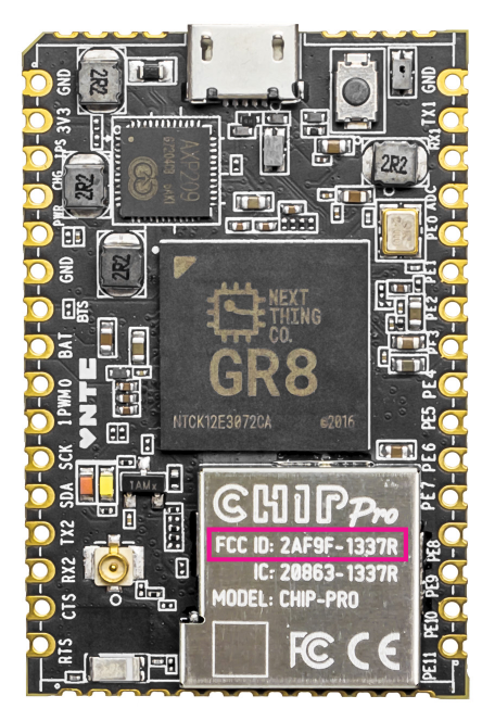
Do Something GR8
Are you thinking of going into mass production, but not sure what path to take? We offer services at several production stages.
- Custom flashing
- NRE software
- Custom engineering support
- PCB material and manufacturer recommendations
If you would like to learn more about how we can help you make a GR8 product, contact us at [email protected].
C.H.I.P v C.H.I.P Pro
C.H.I.P and C.H.I.P Pro have a lot of similarities, but there are some very important distinctions that go beyond the obvious size differences.
| feature | C.H.I.P | C.H.I.P Pro |
|---|---|---|
| RAM | 512 MB | 256 MB |
| Storage | 4GB NAND SLC or 8GB NAND MLC | 512 MB SLC NAND |
| SD Card Interface | Yes, 4-bit | Yes, 4-bit |
| I2S Digital Audio | No | Yes |
| Video Interface | Composite | No |
| Certification | Section 15 | Section 15 Modular |
| Easy to Mass Produce with | No | Yes |
| Easy to Play With | Yes | No |
| Size | Small (40.64 mm x 60.50 mm x 11.2 mm) | Tiny (30 mm x 45 mm x 5.2 mm) |
| Pin Headers | Yes | No |
| Operating System | Debian | Gadget |
| SOC | Allwinner R8 ARM7 | Next Thing GR8 ARM7 |
| Speed | 1 Ghz | 1 Ghz |
| Wifi | B/G/N 2.4GHz (Realtex RTL8723BS) | B/G/N 2.4GHz (Realtex RTL8723DS) |
| Bluetooth | 4.0 | 4.2 |
| PWM | 1 | 2 |
| Audio Input | 1 channel | 2 channel |
If you are looking for a more C.H.I.P-like experience with connectors and LEDS, we recommend the Development Kit.